


Table of Contents
- Introduction of How to Perform Linear Static Analysis in ANSYS APDL
- What is Linear Static Analysis?
- Static vs Dynamic Analysis
- Equations of Motion
- When Should Linear Static Analysis Be Used?
- Complete Linear Static Modeling Workflow
- Geometry Creation
- Element Type Definition
- Section Definition
- Material Properties
- Mesh Generation
- Boundary Conditions
- Load Application
- Solution Settings
- Solving the Model
- Post Processing
- Result Verification
- Engineering Example
- Project Features
- Who Should Use This Project?
Introduction
Linear Static Analysis is one of the most widely used analysis methods in ANSYS APDL and structural engineering.
It is suitable for structures that experience relatively small deformations, remain within the elastic range of the material, and are subjected to static loading conditions.
How to Perform Linear Static Analysis in ANSYS APDL
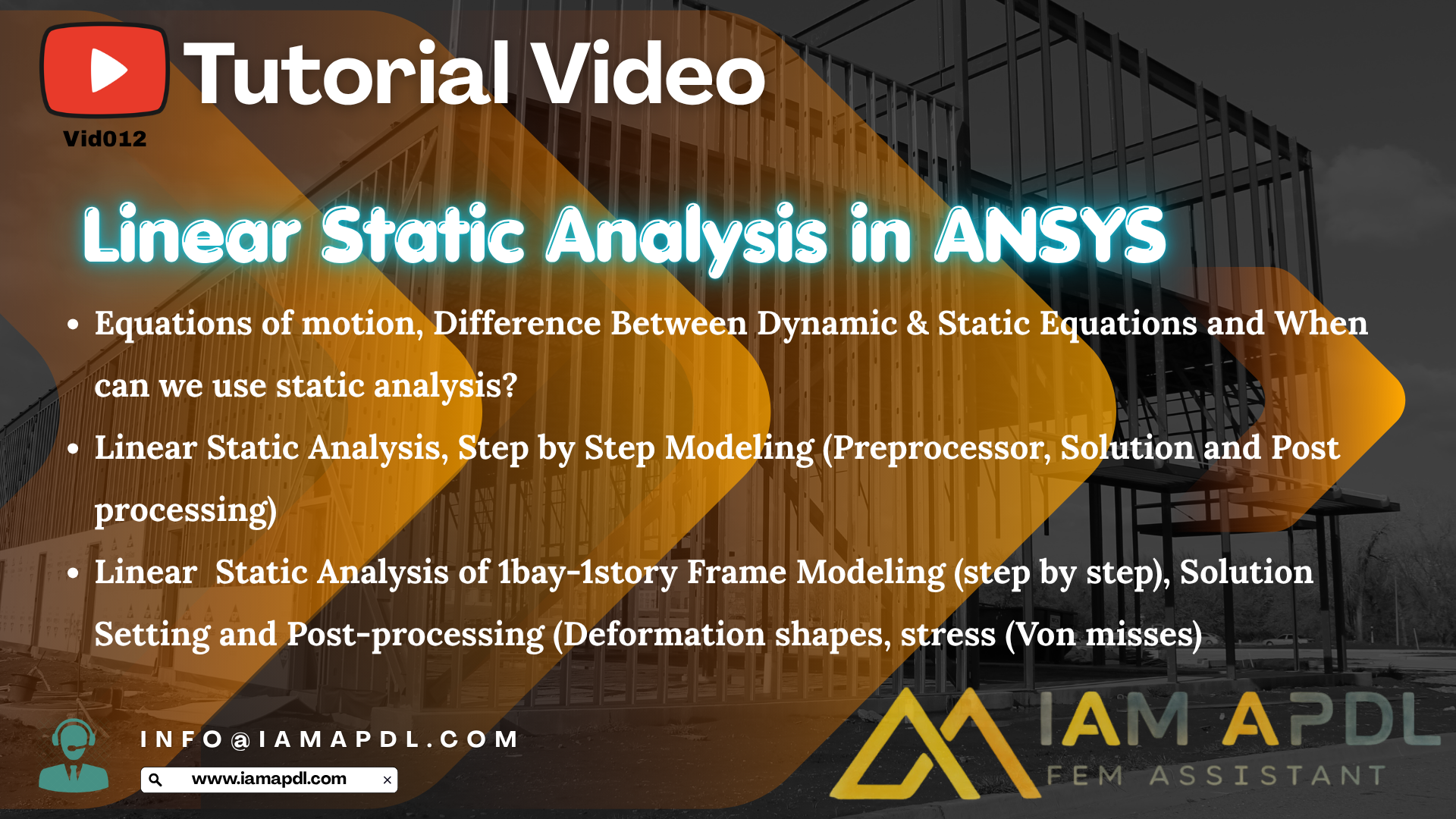
This project teaches the complete workflow of Linear Static Analysis using ANSYS APDL, including theory, APDL programming, graphical modeling, solution settings, post-processing, and engineering interpretation of the results.
What is Linear Static Analysis?
Linear Static Analysis assumes that:
- Material behavior is linear elastic.
- Deformations are small.
- Geometry does not change significantly during loading.
- Loads are applied slowly without inertia effects.
- Structural stiffness remains constant throughout the analysis.
These assumptions make Linear Static Analysis computationally efficient while providing highly accurate results for many engineering structures.
Equations of Motion
Before performing any structural analysis, engineers should understand the governing equations of motion.
The general structural dynamic equation is:Mu¨+Cu˙+Ku=F(t)
where:
- M = Mass Matrix
- C = Damping Matrix
- K = Stiffness Matrix
- u = Displacement
- F = Applied Load
For Linear Static Analysis, inertia and damping effects are neglected, simplifying the equation to:Ku=F
This simplified equation is solved directly by ANSYS APDL to determine structural displacements. How to Perform Linear Static Analysis in ANSYS APDL
Difference Between Static and Dynamic Analysis
This tutorial explains the major differences between Static and Dynamic Analysis.
Linear Static Analysis
- Constant loads
- No inertia effects
- No damping effects
- Small displacement assumption
- Linear material behavior
- Fast computation
Dynamic Analysis
- Time-dependent loading
- Includes inertia effects
- Includes mass matrix
- May include damping
- Can model vibration and earthquake response
- Higher computational cost
Understanding these differences is essential for selecting the appropriate analysis type.
When Can We Use Linear Static Analysis?
Linear Static Analysis is commonly used for:
- Steel structures
- Reinforced concrete structures
- Building frames
- Industrial structures
- Mechanical components
- Pressure vessels
- Support systems
- Bridge components
- Structural verification
- Educational finite element examples
Complete Linear Static Analysis Workflow
The tutorial of How to Perform Linear Static Analysis in ANSYS APDL demonstrates the complete engineering workflow used by professional finite element analysts:
- Geometry Creation
- Element Definition
- Section Definition
- Material Properties
- Mesh Generation
- Boundary Conditions
- Load Application
- Solution Settings
- Solve
- Post Processing
- Verification of Results
Step 1 – Define Geometry
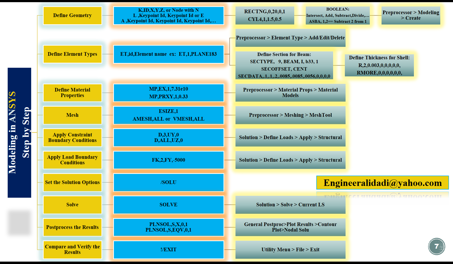
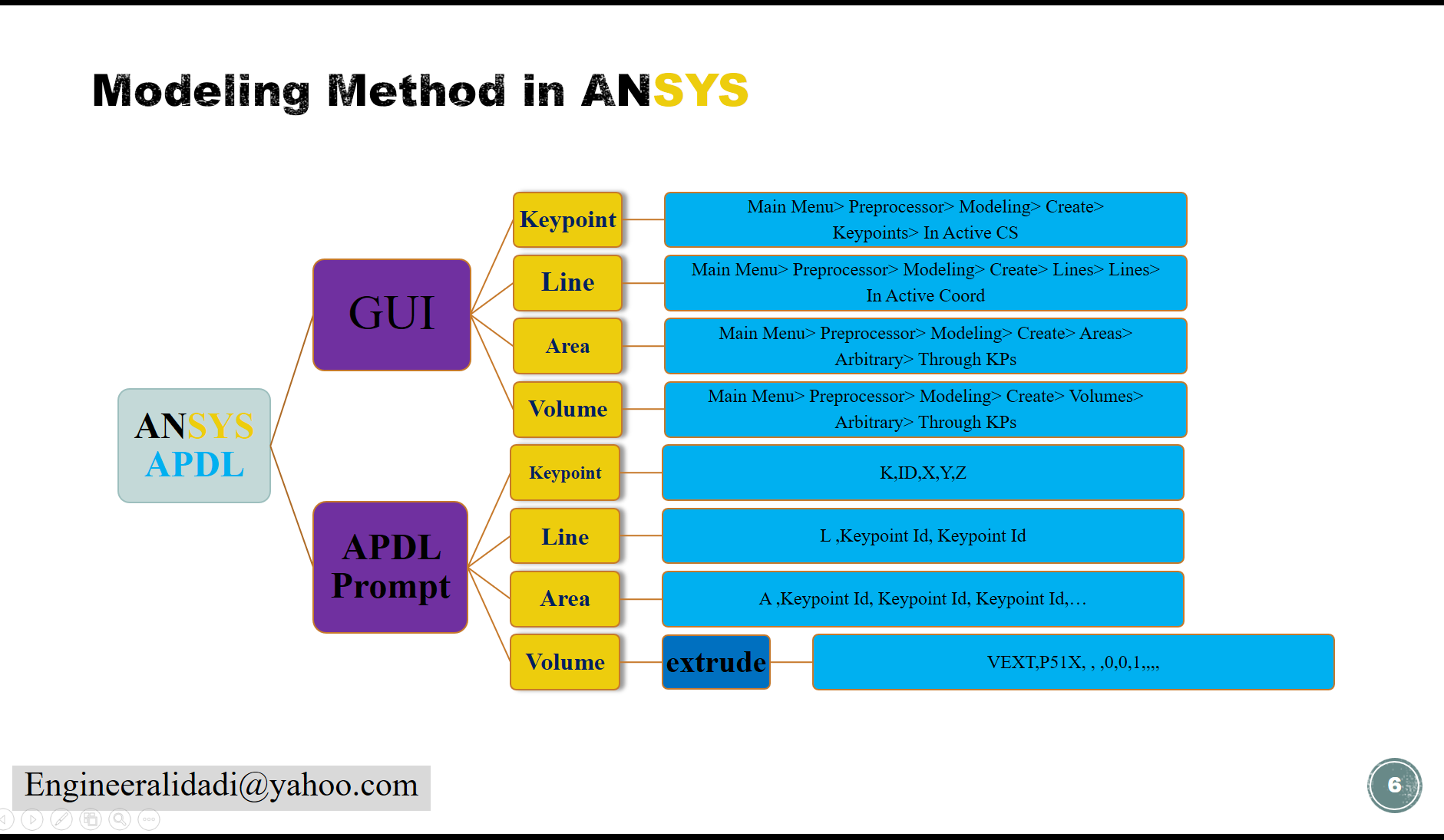
The project in How to Perform Linear Static Analysis in ANSYS APDL explains several methods for creating geometry in ANSYS APDL.
Topics include:
- Keypoints
- Lines
- Areas
- Volumes
APDL Commands:
K,ID,X,Y,Z
N
L
A
RECTNG
CYL4
Boolean operations include:
- Add
- Subtract
- Divide
- Intersect
Example:
ASBA,1,2GUI Path:
Preprocessor → Modeling → Create
Step 2 – Define Element Types
Selecting the appropriate finite element is one of the most important modeling decisions.
This project explains how to define element types such as:
ET,1,PLANE183GUI Path:
Preprocessor → Element Type → Add/Edit/Delete
Step 3 – Define Beam and Shell Sections
Beam section definition:
SECTYPE
SECOFFSET
SECDATA
Shell thickness definition:
R
RMORE
Students learn how different section properties influence structural stiffness and behavior.
Step 4 – Define Material Properties
Material properties are defined using:
MP,EX
MP,PRXY
Mechanical properties include:
- Young’s Modulus (E)
- Poisson’s Ratio (ν)
GUI Path:
Preprocessor → Material Properties → Material Models
Step 5 – Generate the Mesh
Mesh quality has a significant influence on solution accuracy.
The tutorial explains:
- Element Size
- Mesh Density
- Mesh Quality
- Automatic Meshing
APDL Commands:
ESIZE
AMESH
VMESH
GUI Path:
Preprocessor → Meshing → MeshTool
Step 6 – Apply Constraint Boundary Conditions
Proper boundary conditions are essential for obtaining realistic structural responses.
Examples include:
D,3,UY,0
D,ALL,UZ,0
Topics covered:
- Fixed Supports
- Roller Supports
- Symmetry Conditions
- Degrees of Freedom (DOF)
GUI Path:
Solution → Define Loads → Apply → Structural
Step 7 – Apply External Loads
Different loading methods are explained, including:
- Point Loads
- Distributed Loads
- Pressure Loads
- Body Loads
- Inertia Loads
Example:
FK,2,FY,-5000Step 8 – Solution Settings
The project explains the most important Solution Options inside ANSYS.
Topics include:
- Analysis Type
- Load Steps
- Solver Settings
- Convergence
- Output Controls
APDL Command:
/SOLUStep 9 – Solve the Model
Once the model is complete, the finite element equations are solved using:
SOLVEGUI Path:
Solution → Solve → Current Load Step
Step 10 – Post Processing
The project demonstrates professional post-processing techniques, including:
- Deformation Shapes
- Von Mises Stress
- Principal Stress
- Reaction Forces
- Base Shear
- Roof Displacement
Example commands:
PLNSOL,S,X
PLNSOL,S,EQV
GUI Path:
General Postproc → Plot Results → Contour Plot → Nodal Solution
Step 11 – Compare and Verify Results
Finite Element Analysis should never end with simply obtaining colorful contour plots.
This tutorial explains professional verification techniques including:
- Checking support reactions
- Comparing analytical solutions
- Verifying displacement values
- Stress consistency
- Equilibrium verification
- Mesh sensitivity
These procedures ensure the reliability of engineering simulations.
Engineering Example in How to Perform Linear Static Analysis in ANSYS APDL
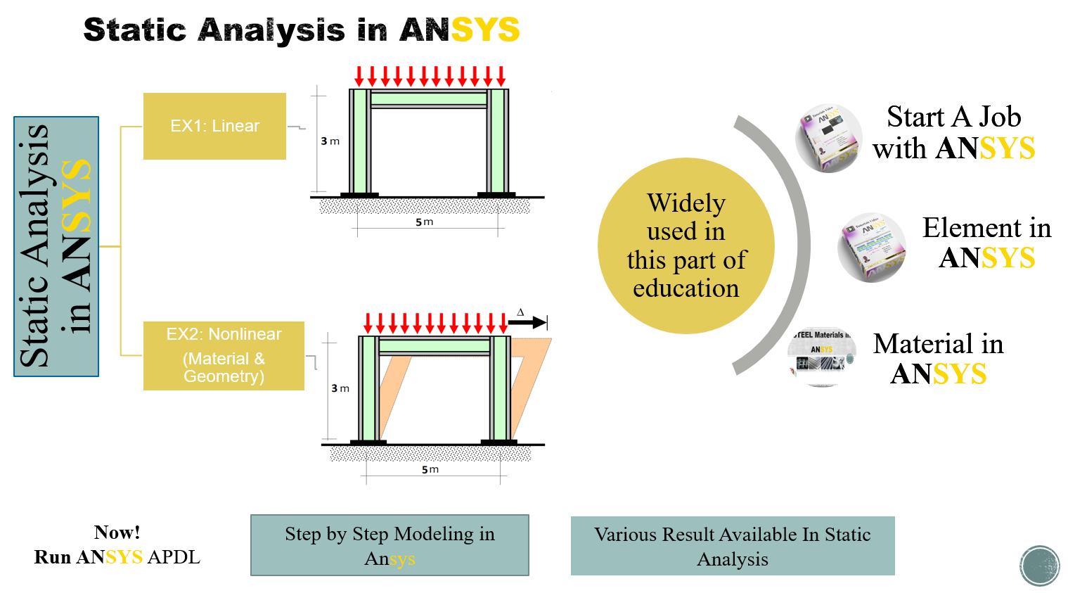
The tutorial includes a complete 1-Bay 1-Story Steel Frame example.
The complete project demonstrates:
- Step-by-step modeling
- APDL programming
- Solution settings
- Deformation visualization
- Von Mises stress distribution
- Base Shear
- Roof Displacement
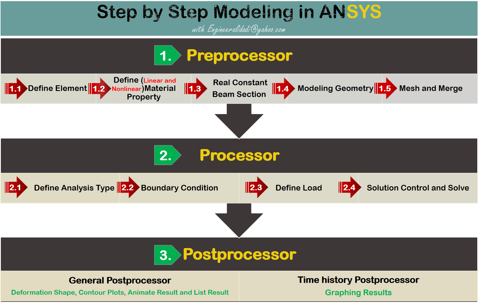
This real engineering example allows students to follow the complete finite element workflow from geometry creation to engineering interpretation.
Project Features
This project includes:
- Complete APDL source code
- Full ANSYS project files
- Step-by-step video tutorial
- Real engineering example
- Structural frame analysis
- Geometry creation
- Meshing strategy
- Material definition
- Boundary condition setup
- Solution settings
- Professional post-processing
- Result verification
Who Should Use This Project?
This tutorial is ideal for:
- Civil Engineers
- Structural Engineers
- Mechanical Engineers
- Graduate Students
- PhD Researchers
- ANSYS Beginners
- ANSYS APDL Users
- Finite Element Analysts
Download Project
Download this complete Linear Static Analysis in ANSYS APDL project to learn professional finite element modeling, APDL programming, structural analysis, solution settings, post-processing, and engineering result verification using a real structural frame example.
YouTube Video
🎥 Watch the complete YouTube tutorial to learn how to perform Linear Static Analysis in ANSYS APDL from start to finish. This lesson explains the theory of static analysis, equations of motion, differences between static and dynamic analysis, complete APDL modeling workflow, solution settings, post-processing, result verification, and engineering interpretation using a real structural frame example.
Related Tutorials Video
Define Soil Material in Ansys APDL
Define Rubber Material in Ansys APDL
How to Solution in ANSYS APDL
post processing in ansys apdl
Reference
Mechanical APDL Element Reference: Chapter 2, Sections 2.12.5
Mechanical APDL Element Reference: Chapter 3, Section 3.1
Mechanical APDL Basic Analysis Guide: Chapter 1, Sections 1.1.2 and 1.1.3
Mechanical APDL Modeling and Meshing Guide: Chapter 2, Section 2.2