



Table of Contents
- Introduction
- Reinforced Concrete Moment Frame with Masonry Infill
- Experimental Specimen Specifications
3.1 Geometric Properties
3.2 Material Properties
3.3 Reinforcement Details
3.4 Experimental Loading System
3.5 Experimental Test Results
- Finite Element Modeling Using ANSYS APDL
4.1 Overview of ANSYS APDL
4.2 Why CONCRETE 65 Element Was Selected
4.3 Step-by-Step Modeling Procedure
- Results Comparison
5.1 Load–Displacement Response
5.2 Crack Pattern Comparison
5.3 Quantitative Comparison
- Conclusion
References
FAQ Section
Related Validation Projects
1. Introduction
Reinforced concrete moment-resisting frames are among the most widely used structural systems in earthquake-resistant buildings. Accurate numerical simulation of their nonlinear behavior is essential for predicting structural performance under lateral loading and for developing reliable design methodologies.
Numerous experimental studies have investigated the seismic behavior of reinforced concrete frames, both with and without masonry infill panels. While masonry infills significantly influence the global response of a structure, the primary objective of this project is not to investigate the contribution of masonry panels. Instead, this validation study focuses exclusively on the structural behavior of the bare reinforced concrete moment frame, allowing the numerical model to be directly compared with the corresponding experimental results of the reinforced concrete frame itself.
A detailed finite element model was developed in ANSYS APDL, and its accuracy was verified against published laboratory data. Particular emphasis was placed on accurately representing concrete nonlinearities, reinforcement behavior, cracking, and global load-displacement response.
Reinforced Concrete Moment Frame FEM Validation
Reinforced concrete moment frames are designed to resist lateral forces through the combined action of beams and columns connected by rigid joints. Their seismic performance depends on complex nonlinear mechanisms including concrete cracking, reinforcement yielding, stiffness degradation, and progressive damage accumulation.
Reliable finite element validation is therefore essential before numerical models are used for research or practical engineering applications.
In this project, only the bare reinforced concrete frame is investigated. Although the original experimental study also examined the influence of masonry infill panels, the present validation focuses solely on the reinforced concrete frame to establish a reliable benchmark for nonlinear finite element modeling using ANSYS APDL.
2. Experimental Specimen Specifications
Reliable experimental data are fundamental for validating nonlinear finite element models.
The experimental benchmark adopted in this project was selected from the well-known study on reinforced concrete frames subjected to lateral loading.
Although the original research also investigated masonry infill panels, only the experimental results of the bare reinforced concrete frame are considered in this validation study. This allows direct assessment of the numerical model without the additional complexity introduced by masonry infill interaction.
2.1 Geometric Properties
The reinforced concrete frame was constructed as a single-bay, single-story specimen with masonry infill.
The beam-column joints, reinforcement layout, and panel dimensions were reproduced according to the experimental study.
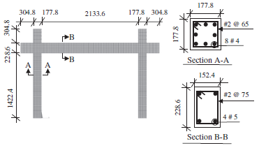
Figure 1: Geometry of the experimental reinforced concrete frame
2.2 Material Properties
Material properties were directly adopted from the experimental investigation.
The finite element model includes:
- Concrete
- Reinforcing steel
- Masonry units
- Mortar properties
The nonlinear constitutive models were calibrated according to experimentally measured mechanical properties.
2.3 Reinforcement Details
Unlike simplified numerical models where reinforcement is uniformly distributed, the longitudinal reinforcing bars in this study were positioned at their actual locations inside beam and column cross-sections.
Similarly, transverse reinforcement was represented according to stirrup spacing defined in the experimental specimen.
This modeling strategy significantly improves the prediction of stiffness degradation and crack propagation.
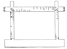
Figure 2: Reinforcement layout of beam and column sections
2.4 Experimental Loading System
The specimen was first subjected to gravity loading equivalent to 294 kN applied on the two columns.
Following the gravity load stage, lateral displacement-controlled loading was applied until significant nonlinear behavior developed.
Using displacement-controlled loading allows accurate comparison between numerical and experimental responses.
2.5 Experimental Test Results
The experimental program investigated:
- Load–displacement relationship
- Initial stiffness
- Crack development
- Yielding of reinforcement
- Concrete crushing
These observations were used as benchmark data for validating the finite element model.
3. Finite Element Modeling Using ANSYS APDL
3.1 Overview of ANSYS APDL
ANSYS Parametric Design Language (APDL) provides a powerful scripting environment for advanced nonlinear structural analysis. Its command-based architecture enables engineers to define geometry, materials, reinforcement, loading procedures, and nonlinear solution strategies with complete flexibility and repeatability.
For reinforced concrete structures, APDL offers specialized element formulations capable of simulating material nonlinearities such as concrete cracking, crushing, and reinforcement interaction. These capabilities make ANSYS APDL one of the most reliable platforms for validating reinforced concrete structures against experimental observations.
3.2 Concrete Modeling Using SOLID65 Element
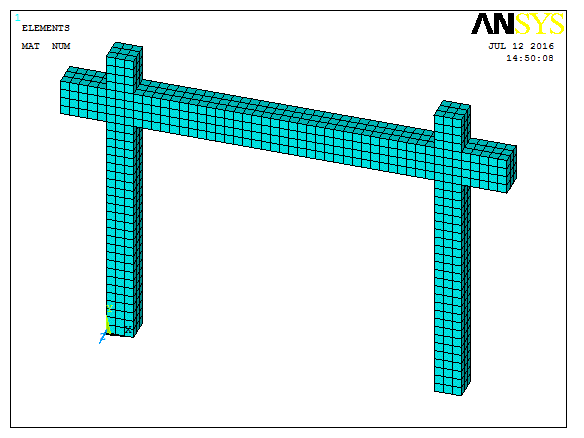
A key feature of this validation project is the use of the SOLID65 finite element for modeling the reinforced concrete frame.
SOLID65 is specifically developed for reinforced concrete applications and is capable of representing the nonlinear behavior of concrete, including tensile cracking and compressive crushing. In addition, the element allows reinforcement effects to be incorporated through smeared reinforcement representation, making it particularly suitable for structural validation studies.
The selection of SOLID65 offers several important advantages:
- Simulation of concrete cracking under tensile stresses.
- Representation of concrete crushing under compression.
- Accurate nonlinear material behavior.
- Capability to include reinforcement effects.
- Proven reliability in reinforced concrete research.
- Extensive validation in academic and engineering applications.
Because of these capabilities, SOLID65 has become one of the most widely used finite elements for nonlinear reinforced concrete modeling in ANSYS APDL.
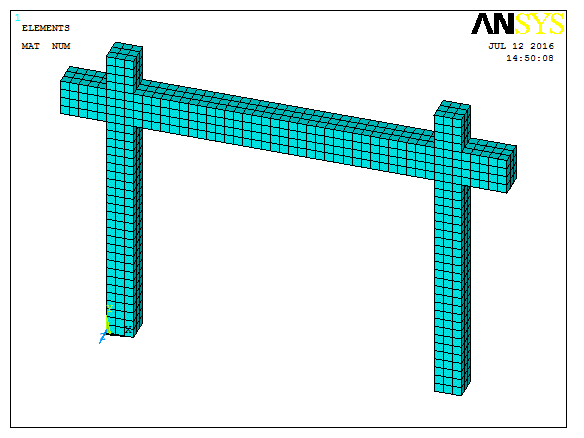
Figure 3: Reinforced concrete frame modeled using SOLID65 elements
3.3 Step-by-Step Modeling Procedure
| Step | Description |
| 1 | Define SOLID65 element |
| 2 | Define nonlinear concrete material |
| 3 | Define reinforcement properties |
| 4 | Create frame geometry |
| 5 | Generate finite element mesh |
| 6 | Apply gravity loading |
| 7 | Apply displacement-controlled lateral loading |
| 8 | Perform nonlinear static analysis |
| 9 | Extract load-displacement response |
4. Results Comparison
The numerical model developed in ANSYS APDL was validated by comparing its response with laboratory measurements.
4.1 Load–Displacement Response
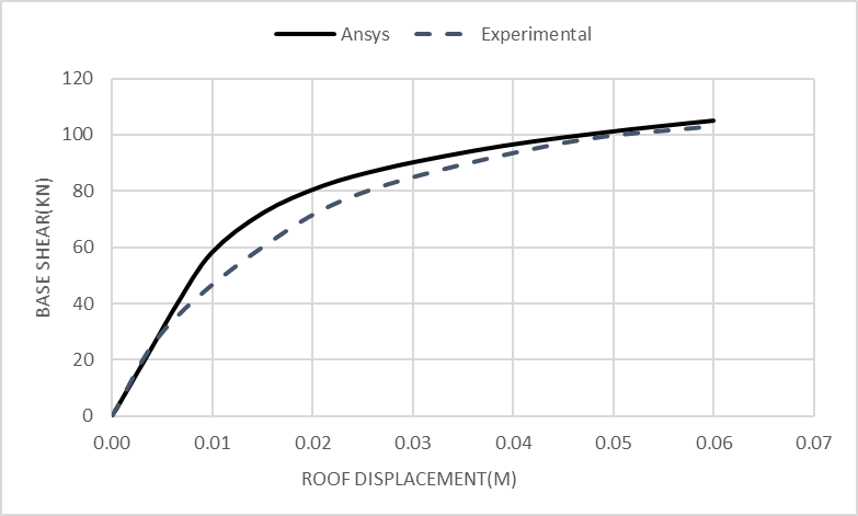
The numerical load–displacement curve shows good agreement with the experimental results throughout the nonlinear loading history.
Although the finite element model slightly overestimates the initial stiffness, the overall structural response closely follows the experimental behavior.
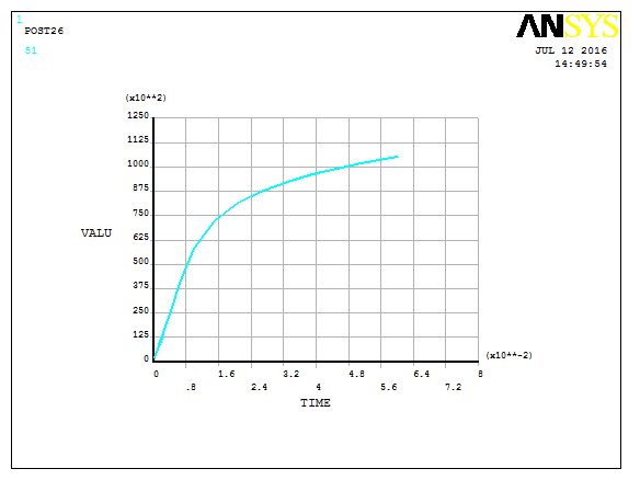
Figure 4: numerical load–displacement curves
4.2 Crack Pattern Comparison
The predicted crack distribution obtained from the numerical model agrees well with the experimentally observed crack pattern.
Both the numerical and experimental results indicate similar crack propagation within beam-column joints and masonry infill.
Figure 5: Yielding patterns
4.3 Quantitative Comparison
| Parameter | Experimental | ANSYS APDL | Error (%) |
| Base Shear | 103 | 104.998 | 2 |
The numerical model reproduces the global structural response with satisfactory accuracy, confirming the effectiveness of the selected modeling strategy and the use of the CONCRETE 65 element.
5. Conclusion
The numerical model developed in ANSYS APDL successfully reproduces the nonlinear response of a bare reinforced concrete moment frame subjected to lateral loading.
Comparison with experimental observations demonstrates good agreement in terms of stiffness, crack development, load-displacement behavior, and overall structural response.
Although the original experimental investigation also examined reinforced concrete frames with masonry infill panels, the present validation is intentionally limited to the bare reinforced concrete frame. This approach provides a clear benchmark for evaluating the numerical modeling strategy without the additional complexity introduced by masonry infill interaction.
One of the most important aspects of this project is the application of the SOLID65 finite element. Its ability to simulate concrete cracking, compressive crushing, and nonlinear material behavior makes it particularly suitable for reinforced concrete validation studies. The successful agreement between numerical predictions and laboratory observations confirms the reliability of the developed ANSYS APDL model for advanced structural research, parametric investigations, and engineering applications.
References
- Mohyeddin, A., et al. FE Modelling of RC Frames with Masonry Infill Panels under In-Plane and Out-of-Plane Loading. Mehrabi, A. B. Experimental Investigation of Reinforced Concrete Frames with Masonry Infill.
- ANSYS, Inc. Mechanical APDL Theory Reference.
FAQ Section
What is RC Frame FEM Validation?
RC Frame FEM Validation is the process of verifying a finite element model of a reinforced concrete frame by comparing numerical predictions with experimental test results.
Why are masonry infill panels important in structural analysis?
Although often considered non-structural, masonry infill panels significantly affect the stiffness, strength, and seismic behavior of reinforced concrete frames.
Why was the CONCRETE 65 element used in this project?
CONCRETE 65 provides accurate representation of beam-column behavior, includes shear deformation based on Timoshenko beam theory, offers excellent numerical stability in nonlinear analysis, and significantly reduces computational cost while maintaining high accuracy.
Is the APDL source code included?
Yes. The complete ANSYS APDL source code used to generate and analyze the validated numerical model is included.
Can this model be used for research purposes?
Yes. The validated model can serve as a reliable benchmark for graduate research, scientific publications, and advanced structural engineering studies.
CTA
Develop reliable nonlinear reinforced concrete simulations with confidence. Download this validated ANSYS APDL project to access the complete APDL source code, experimentally verified finite element model, detailed documentation, and load-displacement comparison for advanced structural engineering research.