Introduction Steel Beam Strengthened with FRP Laminate
Steel Beam Strengthened with FRP Laminate
Experimental Specimen Specifications
3.1 Specimen Geometry
3.2 Material Properties
3.3 Adhesive Properties
3.4 FRP Laminate Properties
3.5 Experimental Test Setup
3.6 Experimental Test Results
Finite Element Modeling Using ANSYS APDL
4.1 Overview of ANSYS APDL
4.2 Modeling of Steel–Epoxy–FRP Composite System
4.3 Step-by-Step Modeling Procedure
Results Comparison
5.1 Load Capacity
5.2 Bond Stress Distribution
5.3 Debonding Failure
5.4 Quantitative Comparison
Conclusion
References
FAQ Section
Related Validation Projects
1. Introduction
Fiber Reinforced Polymer (FRP) composites have become one of the most effective strengthening techniques for deteriorated steel structures due to their high strength-to-weight ratio, corrosion resistance, and ease of installation. Bonding FRP laminates to steel members using structural adhesives allows engineers to significantly improve structural performance without increasing the dead load of the structure.Steel Beam Strengthened with FRP Laminate
However, the effectiveness of externally bonded FRP systems depends primarily on the quality of the adhesive bond between the steel substrate and the FRP laminate. In many practical applications, premature debonding occurs before either the steel member or the FRP laminate reaches its ultimate strength. Consequently, understanding the bond failure mechanism is essential for developing reliable strengthening systems.Steel Beam Strengthened with FRP Laminate
This validation study presents a finite element model developed in ANSYS APDL for a steel member strengthened with externally bonded CFRP laminate. The numerical model is validated against laboratory experiments with particular emphasis on stress transfer through the adhesive layer and the initiation of bond failure.Steel Beam Strengthened with FRP Laminate
Externally bonded FRP laminates are increasingly used to strengthen existing steel structures subjected to fatigue, corrosion, excessive deflection, or increased service loads. The additional stiffness and tensile capacity provided by FRP materials can significantly improve structural performance.
Unlike reinforced concrete strengthening, however, failure in FRP-strengthened steel members is usually governed by the adhesive interface rather than rupture of the steel or the composite laminate.
This validation project focuses on accurately reproducing the bond behavior between steel, epoxy adhesive, and CFRP laminate using ANSYS APDL. The validated numerical model provides engineers and researchers with a reliable benchmark for studying debonding mechanisms and strengthening efficiency.
2. Experimental Specimen Specifications
Reliable experimental data are essential for validating finite element models involving adhesive interfaces.
The experimental benchmark adopted in this study was obtained from laboratory investigations on CFRP-strengthened steel joints designed to evaluate bond behavior under different loading configurations.
Three different joint configurations were investigated experimentally:
Double-Lap Joint (DL)
Single-Lap Joint (SL)
T-Peel Joint (PL)
These configurations represent different combinations of shear and peel stresses acting along the adhesive bondline.
2.1 Specimen Geometry
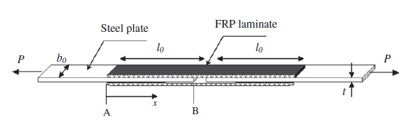
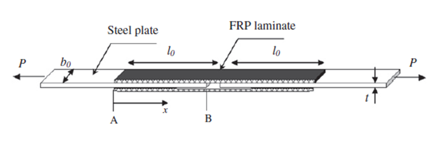
Three different specimen configurations were prepared to investigate the influence of joint geometry on bond behavior.
The specimens differed in bond length, bond width, and loading configuration while maintaining a constant adhesive thickness.
Steel Beam Strengthened with FRP Laminate
Figure 1: Geometry of experimental specimens
2.2 Material Properties
The strengthened system consists of three primary materials:
Structural steel substrate
CFRP laminate
Epoxy adhesive
The experimentally measured mechanical properties were directly adopted in the numerical model.
Steel
Property
Value
Young’s Modulus
196 GPa
Yield Strength
361 MPa
Ultimate Strength
516 MPa
CFRP Laminate
Property
Value
Young’s Modulus
150.8 GPa
Tensile Strength
2492 MPa
Epoxy Adhesive
Property
Value
Tensile Strength
15.5 MPa
2.3 Adhesive Properties
The adhesive layer consisted of a two-component structural epoxy with a uniform thickness of 0.5 mm throughout all specimens.
Since adhesive failure represents the weakest component of the strengthening system, accurate modeling of the adhesive layer is critical for predicting debonding initiation and ultimate bond strength.
2.4 FRP Laminate Properties
A high-strength carbon fiber reinforced polymer (CFRP) laminate was bonded to the steel surface.
The laminate provides additional tensile stiffness while maintaining a very low self-weight, making it an ideal strengthening material for existing steel structures.
2.5 Experimental Test Setup
All specimens were tested using an Instron 5500 universal testing machine under monotonic static loading.
The loading rate was maintained at 0.01 mm/s.
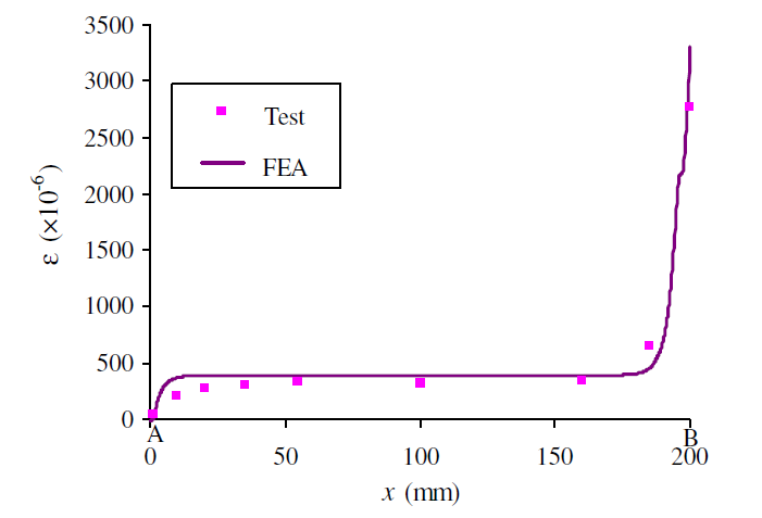
Strain gauges were attached to the outer surface of the CFRP laminate to monitor longitudinal strain development along the bonded length.
Steel Beam Strengthened with FRP Laminate
Figure 2: Experimental test setup
2.6 Experimental Test Results
The experimental investigation evaluated:
Ultimate bond strength
Failure load
Strain distribution
Shear stress concentration
Peel stress concentration
Debonding initiation
The measured responses were used as benchmark data for validation of the finite element model.
3. Finite Element Modeling Using ANSYS APDL
3.1 Overview of ANSYS APDL
ANSYS APDL provides a powerful scripting environment for nonlinear finite element analysis of bonded composite systems.
Its parametric modeling capabilities allow accurate representation of different materials, interface conditions, contact behavior, and nonlinear material properties while maintaining complete control over mesh generation and solution procedures.
3.2 Modeling of Steel–Epoxy–FRP Composite System
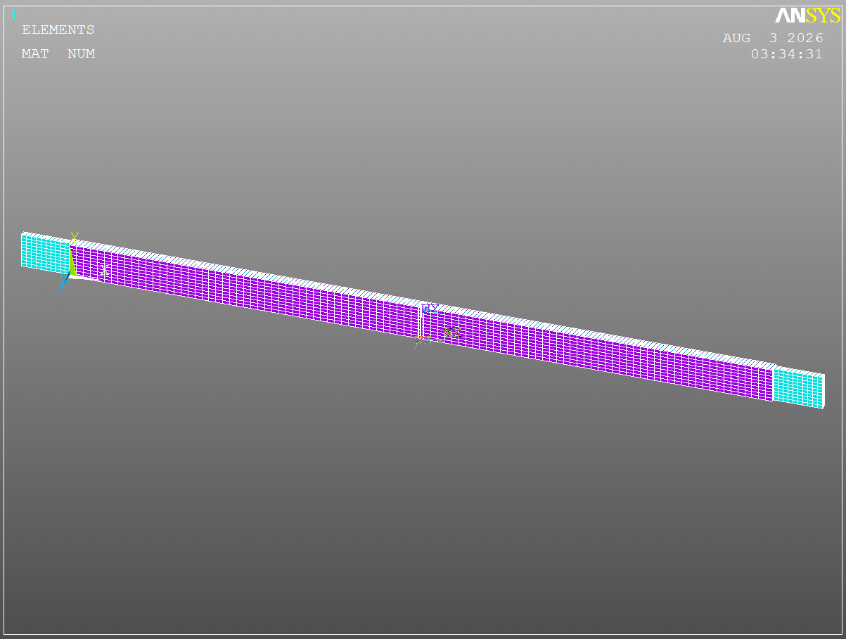
The finite element model explicitly represents the three principal components of the strengthened system:
Steel substrate
Epoxy adhesive layer
CFRP laminate
Each material is assigned its experimentally measured mechanical properties.
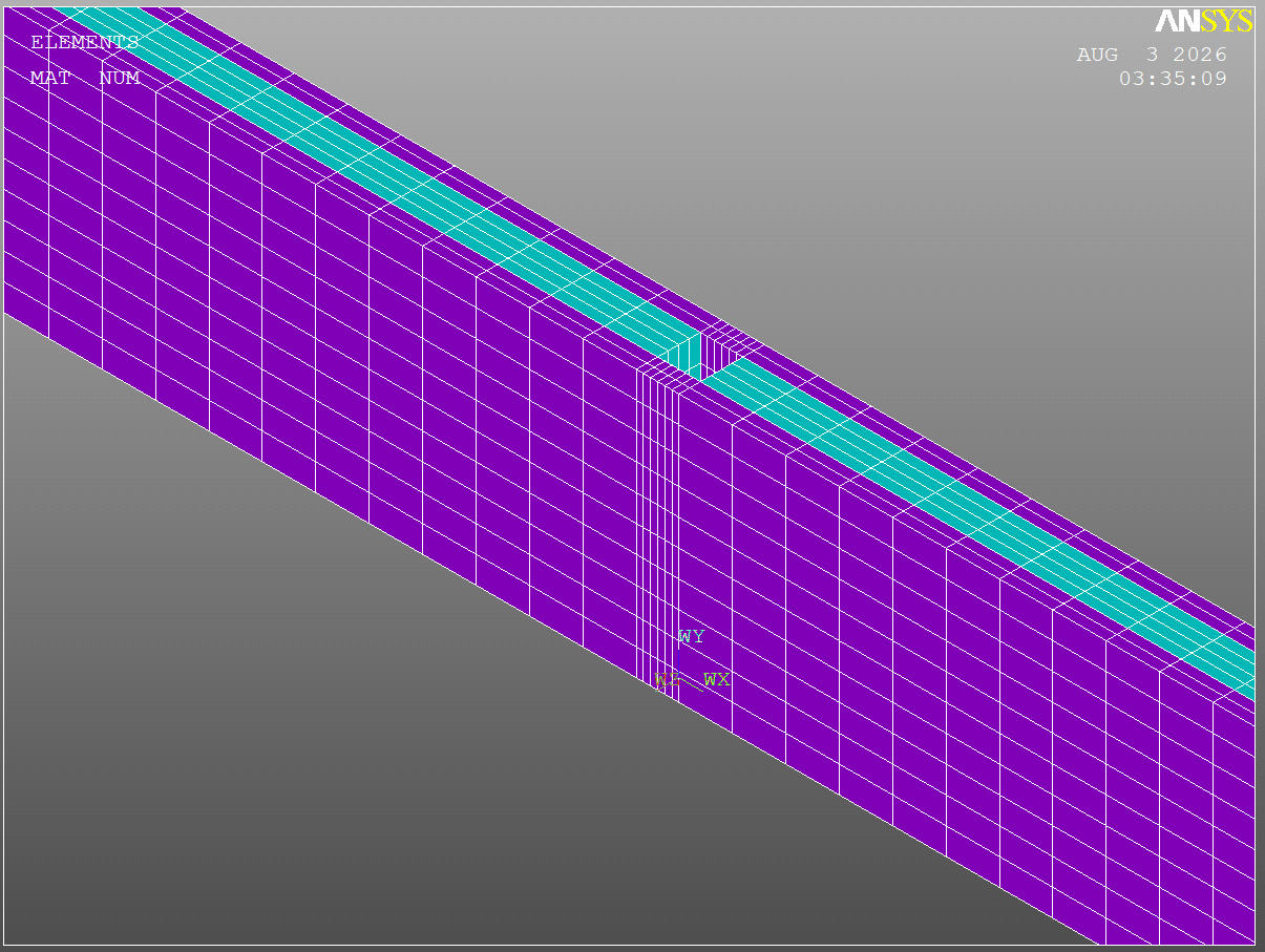
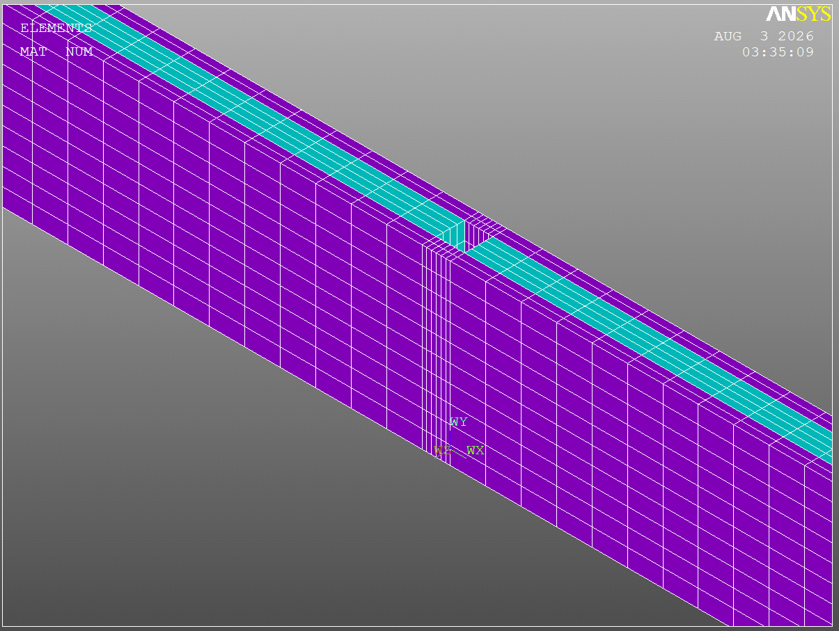
Special attention is devoted to the adhesive layer, where high stress gradients develop near the laminate ends.
Accurate representation of the adhesive interface enables prediction of stress concentrations responsible for premature debonding.
Steel Beam Strengthened with FRP Laminate
Figure 3: ANSYS APDL model of the bonded steel–FRP system
3.3 Step-by-Step Modeling Procedure
Step
Description
1
Define steel material properties
2
Define CFRP laminate properties
3
Define epoxy adhesive properties
4
Create specimen geometry
5
Generate finite element mesh
6
Apply boundary conditions
7
Apply monotonic loading
8
Perform nonlinear analysis
9
Evaluate stress distribution
10
Compare numerical and experimental results
4. Finite Element Modeling Using ANSYS APDL
Steel Beam Strengthened with FRP Laminate
4.1 Overview of ANSYS APDL
The numerical model was entirely developed using ANSYS Mechanical APDL, a command-driven finite element environment that enables complete control over geometry generation, material definitions, meshing strategy, loading procedures, nonlinear analysis, and post-processing.
Unlike graphical interfaces, APDL provides a fully parametric modeling workflow, allowing engineers to rapidly modify specimen dimensions, material properties, loading conditions, and analysis parameters without rebuilding the entire model. This capability is particularly valuable for validation studies, optimization, and extensive parametric investigations.
The scripting-based approach also guarantees repeatability and minimizes human errors commonly associated with manual modeling procedures.
4.2 Parametric Modeling Strategy
One of the main strengths of this numerical model is its fully parametric implementation.
Instead of defining geometric dimensions as fixed values, all important dimensions were introduced as APDL parameters. This approach allows the same model to be reused for different specimen configurations simply by modifying a few variables.
The primary parameters include:
Parameter
Description
b
Specimen width
l0
Bond length
l1
Extension length
ts
Steel plate thickness
tf
CFRP laminate thickness
ta
Adhesive thickness
P
Applied external load
q
Equivalent distributed load
Because all dimensions are parameterized, engineers can easily investigate the influence of bond length, laminate thickness, adhesive thickness, or specimen geometry without modifying the modeling procedure.
This parametric strategy makes the APDL model highly suitable for research-oriented sensitivity analyses and optimization studies.
4.3 Material Modeling
The finite element model consists of three different nonlinear materials representing the actual strengthened system:
Structural Steel
CFRP Laminate
Epoxy Adhesive
Each material was defined using experimentally measured mechanical properties obtained from laboratory testing.
Structural Steel
The steel substrate was modeled using nonlinear elastic-plastic material behavior based on a multilinear isotropic hardening model (MISO).
The complete stress-strain curve obtained from the experimental investigation was implemented directly into ANSYS APDL using multiple material points.
This approach allows the model to accurately capture:
Elastic behavior
Yielding
Plastic hardening
Ultimate stress development
instead of relying on a simplified bilinear approximation.
CFRP Laminate
The CFRP laminate was also represented using experimentally measured nonlinear mechanical properties.
Although FRP behaves almost linearly until failure, implementing the measured stress-strain relationship provides a more realistic numerical representation of the strengthening system.
The model includes:
Young’s Modulus
Poisson’s Ratio
Density
Nonlinear tensile behavior
according to the experimental data reported in the reference study.
Epoxy Adhesive
Special attention was devoted to the adhesive layer because it governs the bond performance between the steel substrate and the CFRP laminate.
Instead of assuming a perfectly elastic adhesive, the epoxy was modeled using a nonlinear constitutive law based on experimentally measured stress-strain data.
The adhesive model includes:
Elastic stiffness
Poisson’s ratio
Density
Nonlinear stress-strain response
This nonlinear representation enables more realistic prediction of stress redistribution within the bondline before debonding initiation.
4.4 Finite Element Selection
Different finite element formulations were employed to accurately represent each component of the strengthened system.
SOLID185
The steel substrate was modeled using the SOLID185 element.
SOLID185 is an eight-node three-dimensional structural solid element capable of representing nonlinear material behavior, plastic deformation, and large strain effects. Its robustness and computational efficiency make it particularly suitable for modeling steel members subjected to nonlinear loading.
PLANE82
The adhesive layer was modeled using PLANE82, an eight-node quadratic element with midside nodes that provides excellent accuracy for capturing stress concentrations and strain gradients.
Because adhesive failure is governed by localized stress concentrations near the laminate ends, using a higher-order element significantly improves numerical accuracy compared with linear elements.
The use of PLANE82 enables accurate evaluation of:
Shear stress distribution
Peel stress
Local stress concentrations
Bondline deformation
which are the governing parameters in adhesive debonding problems.
4.5 Nonlinear Material Definition
Rather than employing simplified linear elastic material models, all primary materials were assigned nonlinear constitutive behavior based on laboratory measurements.
The multilinear isotropic hardening (MISO) formulation was adopted for materials exhibiting nonlinear behavior, allowing the finite element model to closely reproduce the experimentally observed response.
This modeling strategy substantially improves prediction accuracy when compared with simplified elastic analyses.
4.6 Advantages of the Developed APDL Model
The developed numerical model offers several advantages:
Fully parametric APDL implementation.
Easy modification of specimen dimensions.
Automatic updating of all geometric variables.
Nonlinear material modeling based on experimental data.
Separate representation of steel, adhesive, and CFRP laminate.
High-order finite elements for improved stress prediction.
Accurate simulation of stress concentration near bond ends.
Efficient platform for future parametric and optimization studies.
Excellent reproducibility due to script-based modeling.
5. Results Comparison
The finite element predictions were compared with experimental observations to evaluate the accuracy of the developed numerical model.
5.1 Load Capacity
The numerical model accurately predicts the ultimate bond capacity measured during laboratory testing.
5.2 Bond Stress Distribution
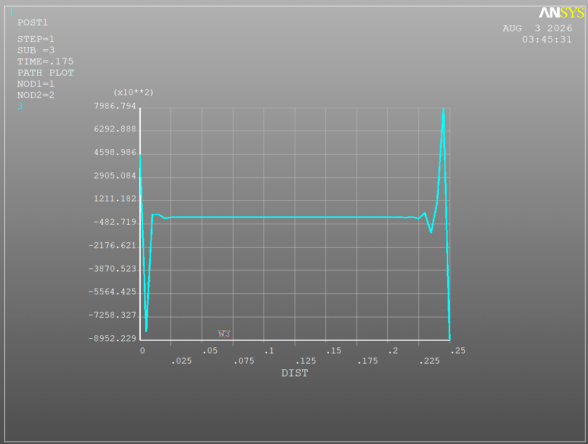
Stress concentrations develop near the ends of the bonded laminate.
The numerical model successfully captures the rapid increase of both shear and normal stresses in these critical regions.
Steel Beam Strengthened with FRP Laminate
Figure 4: Shear stress distribution along the adhesive bondline
5.3 Debonding Failure
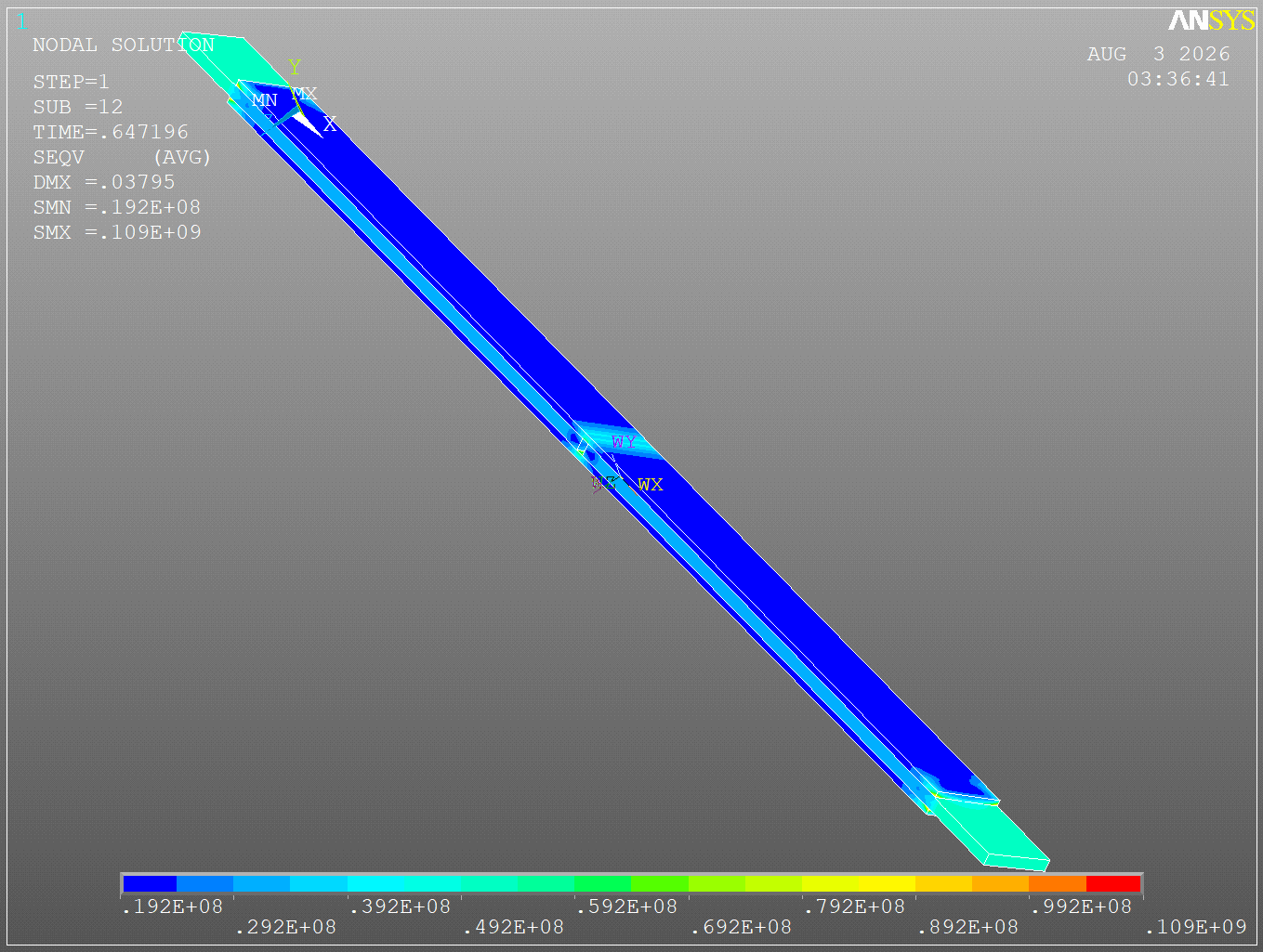
The numerical analysis correctly predicts adhesive debonding at the steel–epoxy interface.
Consistent with experimental observations, failure initiates before either the steel substrate or the CFRP laminate reaches its ultimate capacity.
The predicted failure mode agrees well with the laboratory results.
Steel Beam Strengthened with FRP Laminate
Figure 5: Experimental versus numerical debonding failure
5.4 Quantitative Comparison
6. Conclusion
The developed ANSYS APDL finite element model successfully reproduces the bond behavior of steel members strengthened with externally bonded CFRP laminates.
The comparison between numerical predictions and laboratory measurements demonstrates good agreement in terms of ultimate load capacity, stress distribution, and adhesive debonding behavior.
The study confirms that the adhesive layer governs the structural response of the strengthening system. High stress concentrations near the laminate ends initiate debonding before failure of either the steel substrate or the CFRP laminate.
The validated model provides a reliable benchmark for future investigations on FRP-strengthened steel structures and can be confidently employed for research studies, optimization of bonded strengthening systems, and advanced structural engineering applications.
It is the process of verifying a finite element model of a steel member strengthened with bonded FRP laminate by comparing numerical predictions with experimental test results.
Why is bond failure important?
The adhesive interface is typically the weakest component of an FRP-strengthened steel system. Premature debonding often governs the ultimate capacity of the strengthened member.
What causes adhesive debonding?
Debonding is mainly initiated by high shear and peel stress concentrations near the ends of the bonded laminate.
Does this package include the ANSYS APDL source code?
Yes. The package contains the complete APDL model together with the validated finite element procedure.
Who can benefit from this validation project? Graduate students, researchers, and structural engineers working on FRP strengthening, bonded composite systems, finite element analysis, and rehabilitation of steel structures.
CTA
Simulate FRP-strengthened steel structures with confidence. Download this validated ANSYS APDL project to access the complete APDL source code, experimentally verified finite element model, bond failure simulation, and comprehensive documentation for advanced structural engineering research.