

Table of Contents
- Introduction Steel Moment Frame & Braced Frame Modeling in ANSYS APDL
- Structural Systems Overview
- 2.1 Steel Moment Resisting Frames (SMRF)
- 2.2 Steel Concentrically Braced Frames (SCBF)
- Structural Design in ETABS
- 3.1 Design Codes
- 3.2 Structural Configuration
- 3.3 Member Design
- Finite Element Modeling in ANSYS APDL
- 4.1 Why ANSYS APDL?
- 4.2 Modeling Strategy
- 4.3 Structural Elements
- 4.4 Material Definition
- 4.5 Boundary Conditions
- 4.6 Diaphragm Modeling
- Modal Analysis
- 5.1 Analysis Procedure
- 5.2 Natural Frequencies
- 5.3 Mode Shapes
- Nonlinear Static (Pushover) Analysis
- 6.1 Analysis Method
- 6.2 Capacity Curve
- 6.3 Plastic Hinge Development
- 6.4 Structural Performance
- Engineering Discussion
- Conclusion
- Frequently Asked Questions
- Related ANSYS APDL Training
1. Introduction
Steel structures are among the most widely used structural systems for residential, commercial, and industrial buildings because of their high strength-to-weight ratio, excellent ductility, rapid construction, and outstanding seismic performance. Their ability to undergo significant inelastic deformation while maintaining structural integrity makes them one of the preferred choices for earthquake-resistant design.Steel Moment Frame & Braced Frame Modeling in ANSYS APDL
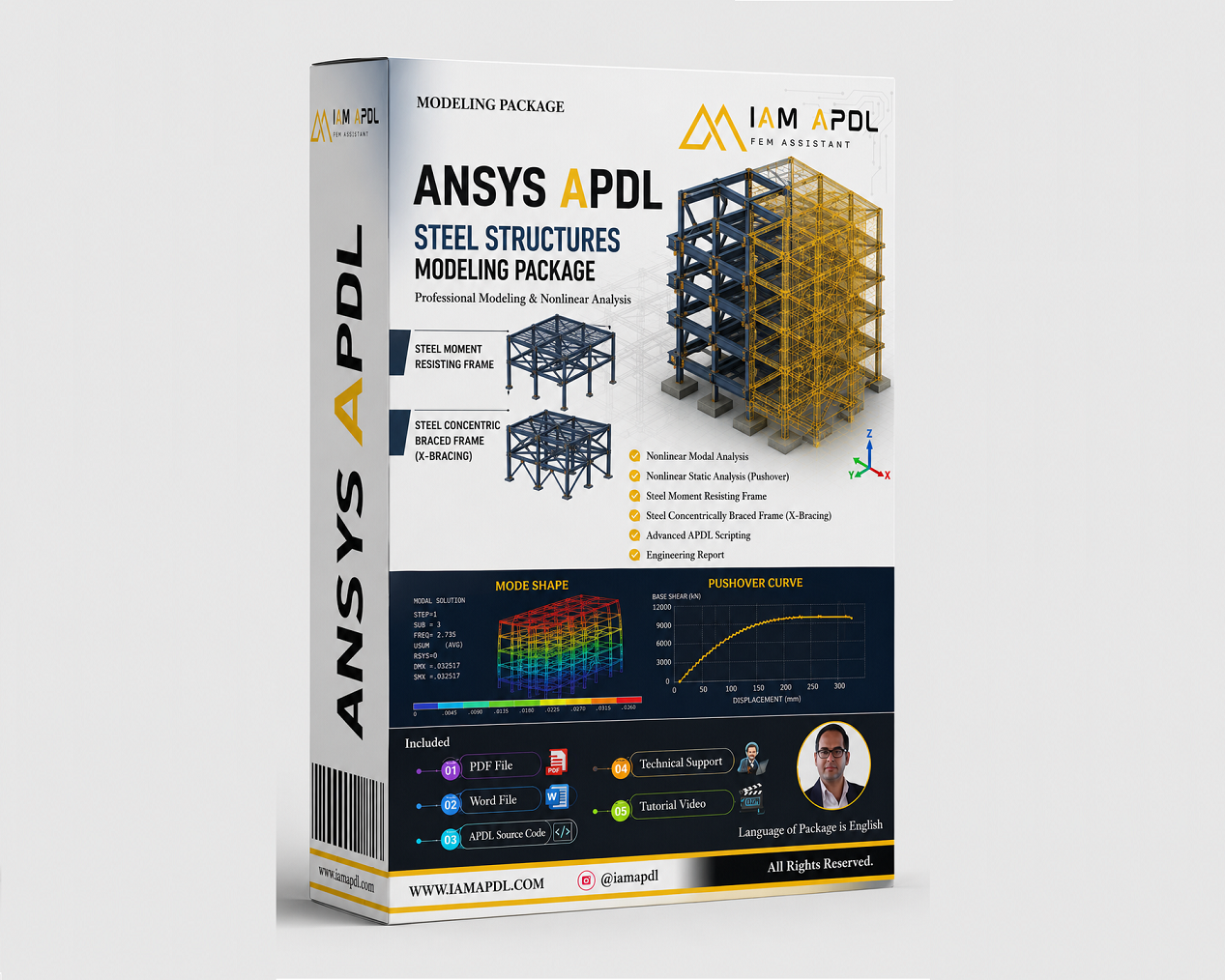
This project presents the complete finite element modeling of two common steel structural systems using ANSYS APDL.
Steel Moment Frame & Braced Frame Modeling in ANSYS APDL
Unlike simplified educational examples, all structural models are based on realistic engineering buildings that were initially designed according to modern steel design provisions using ETABS and then reproduced in ANSYS APDL for advanced finite element analysis.
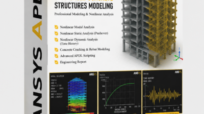
The package includes four complete three-dimensional structural models:
- 3-Story Steel Moment Resisting Frame
- 10-Story Steel Moment Resisting Frame
- 3-Story Steel Concentrically Braced Frame
- 10-Story Steel Concentrically Braced Frame
The primary objective is to demonstrate the influence of structural height and lateral load resisting system on the global seismic behavior of steel buildings.
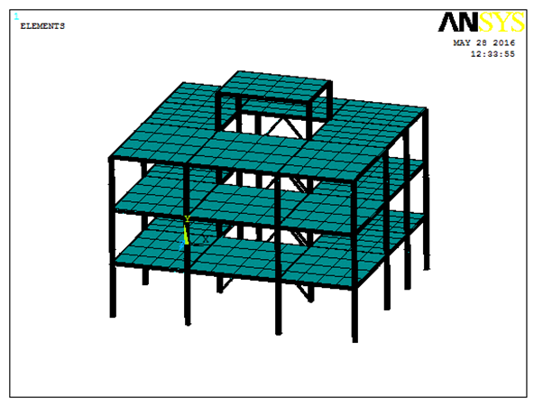
Figure 1. Three-dimensional overview of the analyzed steel structures.
2. Structural Systems Overview
2.1 Steel Moment Resisting Frames (SMRF)
Steel Moment Resisting Frames resist lateral loads primarily through the flexural stiffness of beams and columns connected by rigid moment-resisting joints.
These systems provide:
- High ductility
- Excellent energy dissipation
- Stable nonlinear behavior
- Superior deformation capacity
They are widely used in regions with high seismic hazards where structural ductility plays a critical role in earthquake performance.
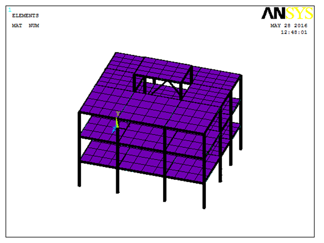
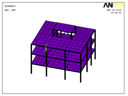
Figure 2. Typical Steel Moment Frame.
2.2 Steel Concentrically Braced Frames (SCBF)
Steel Concentrically Braced Frames utilize diagonal steel braces to transfer lateral forces directly to the foundation.
Steel Moment Frame & Braced Frame Modeling in ANSYS APDL
Compared to moment frames, SCBF systems generally provide:
- Higher lateral stiffness
- Smaller inter-story drift
- Reduced structural displacement
- Economical seismic design
The comparison between SMRF and SCBF enables engineers to understand the advantages and limitations of each structural system.
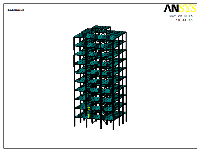
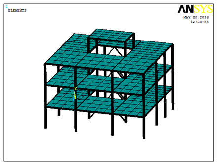
Figure 3. Steel Braced Frame Model.
3. Structural Design in ETABS
Prior to finite element modeling, all buildings were designed in ETABS according to current structural design provisions.
Steel Moment Frame & Braced Frame Modeling in ANSYS APDL
The structural design process included:
- Definition of structural geometry
- Gravity loading
- Seismic loading
- Steel member design
- Member optimization
- Final section selection
The final member sections obtained from ETABS were directly implemented in the ANSYS APDL models.
This workflow ensures that the finite element models accurately represent practical engineering structures rather than theoretical examples.
4. Finite Element Modeling in ANSYS APDL
4.1 Why ANSYS APDL?
ANSYS APDL offers a fully parametric scripting environment capable of modeling complex structural systems with exceptional flexibility and precision.
Unlike graphical modeling environments, APDL enables engineers to automate every stage of model generation, loading, solution, and post-processing.
The scripting methodology presented in this project follows the same professional workflow used in real engineering projects.
For users interested in learning each command in detail, complete educational videos are available through the I AM APDL training platform, where every stage of professional structural modeling is explained step by step.
4.2 Modeling Strategy
Each structural model was generated parametrically using APDL commands.
The modeling procedure includes:
- Structural grid generation
- Automatic node creation
- Beam and column generation
- Floor modeling
- Material assignment
- Section assignment
- Boundary conditions
- Load definition
- Solution control
The fully parametric structure of the code allows users to modify building dimensions, story numbers, member sections, and loading conditions with minimal effort.
4.3 Structural Elements
Structural members were modeled using BEAM189, one of the most advanced beam elements available in ANSYS for slender steel members.
Floor slabs were modeled using Shell Elements to represent diaphragm action and realistic floor stiffness.
The use of BEAM189 provides:
- Accurate geometric stiffness
- Large displacement capability
- Nonlinear material compatibility
- Efficient computational performance
Detailed implementation of BEAM189 and Shell elements is fully covered in the corresponding educational tutorials available on the I AM APDL platform.
4.4 Material Definition
Steel material properties were defined using nonlinear constitutive models to accurately simulate yielding during pushover analysis.
Material parameters include:
- Young’s Modulus
- Poisson’s Ratio
- Density
- Yield Stress
- Plastic Hardening
The nonlinear material implementation follows standard structural engineering practice.
4.5 Boundary Conditions
The supports were modeled as fixed supports at the foundation level.
Rigid diaphragm constraints were assigned to every floor to ensure realistic lateral load distribution among structural members.
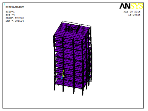
5. Modal Analysis
Modal analysis was performed to investigate the dynamic characteristics of each structural model.
Following common engineering practice, a sufficient number of vibration modes equivalent to approximately three times the number of stories were extracted.
The modal analysis provides:
- Natural frequencies
- Natural periods
- Mode shapes
- Mass participation ratios
These parameters form the basis for understanding the dynamic response of steel buildings under seismic excitation.
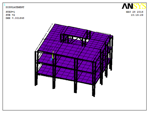
6. Nonlinear Static (Pushover) Analysis
The nonlinear static analysis was carried out using displacement-controlled loading.
The analysis gradually increased the roof displacement until significant yielding developed throughout the structural system.
The results include:
- Capacity Curve
- Progressive yielding
- Plastic hinge formation
- Structural stiffness degradation
- Ultimate structural capacity
The nonlinear solution strategy implemented in APDL is discussed comprehensively in the corresponding training videos available through the I AM APDL educational platform.
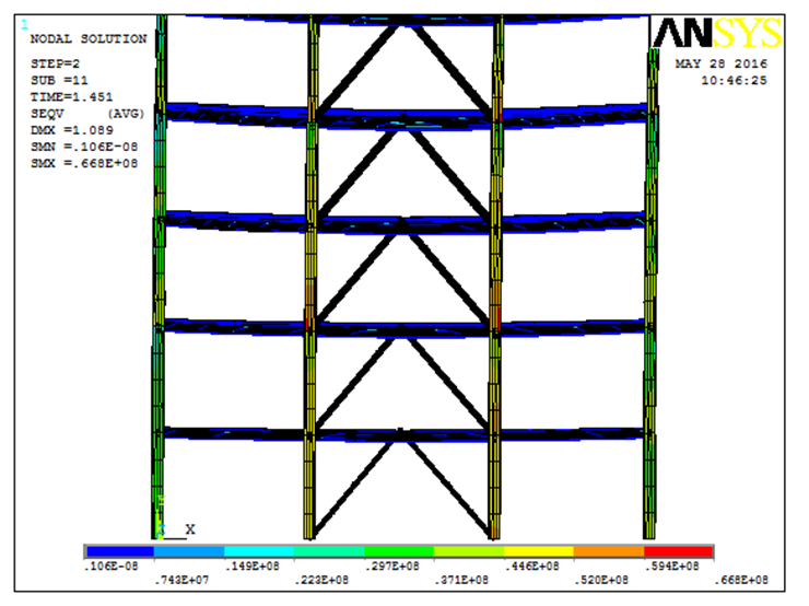
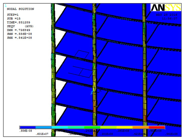
Figure 10. Pushover loading configuration.
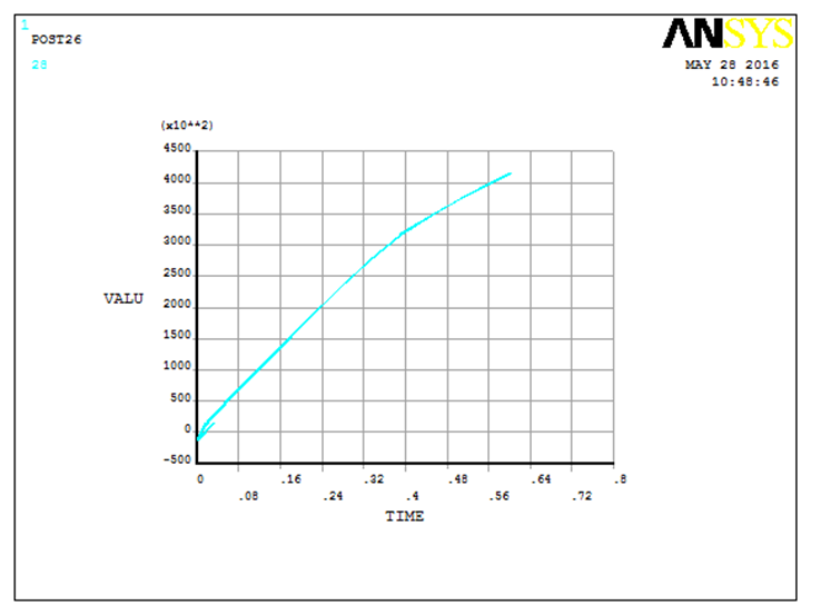
Figure 11. Capacity curve.
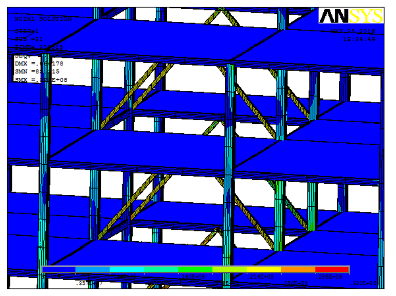
Figure 14. Final nonlinear deformation.
7. Engineering Discussion
The comparative analyses demonstrate clear behavioral differences between Steel Moment Resisting Frames and Steel Concentrically Braced Frames.
The moment frame systems exhibit greater structural flexibility and higher deformation capacity, allowing extensive plastic hinge development and superior energy dissipation under increasing lateral displacement.
Conversely, the concentrically braced frame systems provide significantly greater lateral stiffness, effectively reducing roof displacement and improving resistance to seismic forces through axial action in the braces.
The comparison between three-story and ten-story structures further illustrates the influence of building height on global stiffness, vibration characteristics, and nonlinear structural response.
These case studies provide valuable engineering insight into the selection of appropriate lateral force-resisting systems for practical building design.
8. Conclusion
This project demonstrates a complete professional workflow for modeling and analyzing steel buildings using ANSYS APDL.
Beginning with structural design in ETABS and continuing through parametric APDL scripting, modal analysis, and nonlinear pushover analysis, the package presents a practical methodology applicable to both academic research and engineering practice.
The combination of fully editable APDL source codes, detailed engineering documentation, and comprehensive educational resources enables users not only to reproduce the presented models but also to develop advanced steel structural models for their own research and design projects.
Frequently Asked Questions
What structural systems are included in this project?
Steel Moment Resisting Frames (SMRF) and Steel Concentrically Braced Frames (SCBF).
How many building models are included?
Four complete three-dimensional structural models.
Which finite element is used for beams and columns?
BEAM189.
Are floor slabs included?
Yes. Floor diaphragms are modeled using Shell elements.
Are APDL source codes included?
Yes. Fully editable APDL scripts are included.
Does the package include tutorial references?
Yes. Each modeling stage is supported by dedicated I AM APDL educational videos.
Related Projects