



Table of Contents
- Introduction RC Beam-Column Joint
- Experimental Specimen Specifications
2.1 Geometric Properties
2.2 Material Properties
2.3 Loading System
2.4 Experimental Results - Finite Element Modeling (ANSYS APDL)
3.1 Overview of ANSYS APDL
3.2 Modeling Procedure (Step-by-Step) - Results Comparison
4.1 Quantitative Comparison - Conclusion RC Beam-Column Joint
References
FAQ
Related Validation Projects
- Introduction
This report presents the validation of a nonlinear finite element model developed for a reinforced concrete beam-column joint using ANSYS Parametric Design Language (APDL). The objective is to verify the accuracy of the numerical model by comparing its response with experimental laboratory results reported in the reference study.
Although the original experimental research investigates both unstrengthened and FRP-strengthened beam-column joints, this validation package focuses exclusively on the unstrengthened control specimen. The purpose is to establish a reliable nonlinear finite element model capable of accurately reproducing the structural behavior of the original reinforced concrete joint before introducing any strengthening technique.
The validation compares the numerical predictions with experimental observations in terms of load-displacement response, stiffness, cracking behavior, failure mechanism, and ultimate load capacity. A close agreement between experimental and numerical results demonstrates the reliability of the developed ANSYS APDL model for advanced nonlinear structural analyses
RC Beam-Column Joint
RC Beam-Column Joint FEM Validation
Beam-column joints are among the most critical regions of reinforced concrete moment-resisting frames, particularly under seismic loading. Their structural performance significantly influences the overall strength, ductility, and energy dissipation capacity of RC buildings.
Accurate numerical simulation of these joints requires realistic representation of concrete cracking, reinforcement yielding, nonlinear material behavior, and complex stress transfer mechanisms within the joint region.
The present validation project reproduces the experimental control specimen using ANSYS APDL. The numerical model accurately captures the nonlinear response of the reinforced concrete joint and provides a reliable basis for future research on strengthened beam-column connections.
- Experimental Specimen Specifications
For the validation process, an experimentally tested reinforced concrete beam-column joint reported in the reference study was selected. Although the original investigation includes strengthened specimens, only the unstrengthened control specimen has been considered in this project to evaluate the accuracy of the developed finite element model.
The experimental program provides complete information regarding specimen geometry, reinforcement layout, concrete properties, loading conditions, and structural response.RC Beam-Column Joint
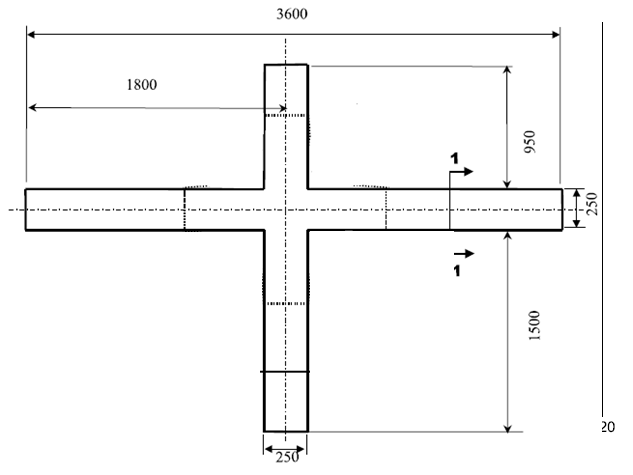
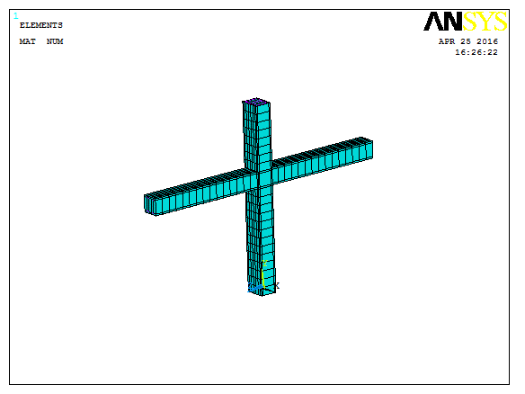
Figure 1. Experimental RC beam-column joint specimen.
2.1 Geometric Properties
The experimental specimen consists of a full-scale reinforced concrete beam-column joint representative of moment-resisting frame construction.
The specimen includes:
• Reinforced concrete beam
• Reinforced concrete column
• Joint core region
• Longitudinal reinforcement
• Transverse reinforcement (stirrups)
All geometric dimensions and reinforcement details were reproduced according to the experimental investigation.
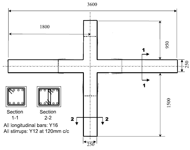
Figure 2. Specimen dimensions and reinforcement details.
2.2 Material Properties
The numerical model employs experimentally measured material properties reported in the reference paper.
The constitutive models include:
• Nonlinear concrete behavior
• Elastic-plastic reinforcing steel
• Concrete cracking
• Concrete crushing
• Reinforcement yielding
These material properties enable accurate simulation of the structural response throughout the nonlinear loading process.
2.3 Loading System
The experimental specimen was subjected to constant axial loading on the column together with gradually increasing lateral displacement applied at the beam end.
The finite element model reproduces the laboratory loading conditions by applying:
• Appropriate boundary conditions
• Constant axial load
• Incremental displacement-controlled lateral loading
• Geometric and material nonlinearities
This loading procedure allows accurate simulation of joint stiffness degradation, crack development, and ultimate failure.
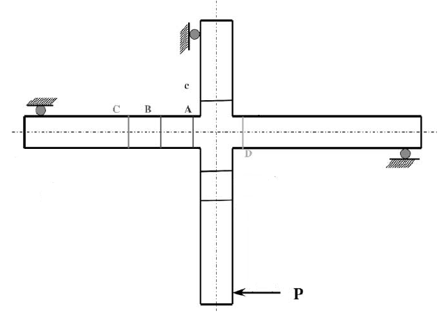
Figure 3. Experimental loading configuration.
2.4 Experimental Results
The primary response parameter used for validation is the lateral load-displacement relationship obtained during the laboratory test.
Additional observations include:
• Crack initiation
• Crack propagation
• Reinforcement yielding
• Joint deformation
• Failure mode
• Ultimate lateral resistance
These experimental observations are used as the benchmark for validating the finite element model.
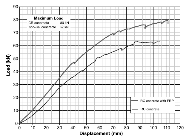
Figure 4. Experimental Load–Displacement Curve.
- Finite Element Modeling (ANSYS APDL)
3.1 Overview of ANSYS APDL
The complete finite element model was developed using ANSYS Parametric Design Language (APDL), providing full control over geometry creation, material definition, reinforcement modeling, nonlinear solution procedures, and post-processing.
Unlike graphical modeling environments, APDL allows highly automated and fully parametric modeling, making it particularly suitable for nonlinear validation studies involving reinforced concrete structures.
The APDL source code included in this package enables complete reproduction of the numerical model. Detailed implementation procedures are also explained in the corresponding ANSYS APDL tutorial videos available on our website.
Advantages of APDL
• Fully parametric scripting
• Automated modeling workflow
• Advanced nonlinear material definition
• Accurate convergence control
• Repeatable numerical simulations
• Efficient parametric studies
3.2 Modeling Procedure (Step-by-Step)
The reinforced concrete beam-column joint was modeled using appropriate nonlinear finite elements capable of representing concrete cracking, reinforcement yielding, and overall structural behavior.
Finite Elements Used
Structural Component ANSYS Element
Concrete SOLID65
Longitudinal Reinforcement LINK8
Transverse Reinforcement LINK8
The numerical modeling procedure consists of:
- Definition of nonlinear concrete material properties.
- Definition of reinforcing steel material properties.
- Creation of beam-column joint geometry.
- Modeling of longitudinal reinforcement.
- Modeling of transverse reinforcement (stirrups).
- Generation of finite element mesh.
- Application of boundary conditions.
- Application of axial and lateral loading.
- Nonlinear solution using incremental load steps.
- Extraction of structural response and failure behavior.
The concrete is modeled using the SOLID65 element, which accurately represents tensile cracking and compressive crushing. Both longitudinal and transverse reinforcing bars are modeled using LINK8 elements embedded within the concrete mesh, allowing realistic simulation of reinforcement yielding and composite action.
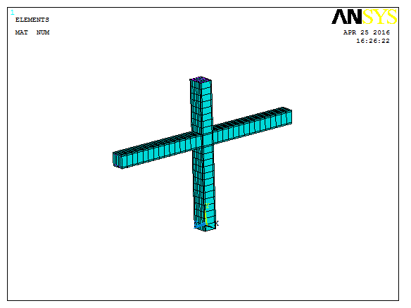
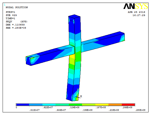
Figure 5. Finite element model developed in ANSYS APDL.
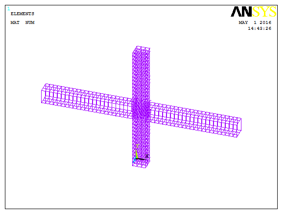
Figure 6. Reinforcement modeling and finite element mesh.
- Results Comparison
4.1 Quantitative Comparison
The numerical results obtained from ANSYS APDL show good agreement with the laboratory observations.
The finite element model successfully predicts:
• Initial stiffness
• Nonlinear response
• Crack development
• Reinforcement yielding
• Ultimate lateral capacity
• Overall failure mechanism
The comparison between experimental and numerical load-displacement curves demonstrates that the adopted modeling methodology accurately reproduces the behavior of the reinforced concrete beam-column joint.
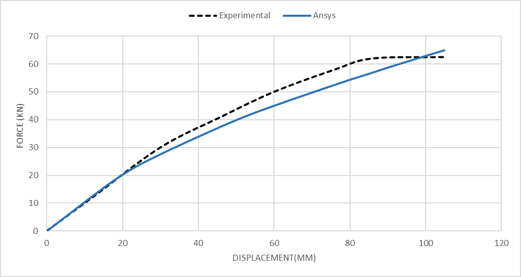
Figure 7. Comparison between experimental and numerical Load–Displacement curves.
| Comparison Parameter | Experimental | ANSYS APDL | Error (%) |
| Ultimate Load | 62.5 | 64 | 2.4 |
Comparison Parameter Experimental ANSYS APDL Error (%)
The low percentage error confirms the suitability of the selected finite elements, material models, and nonlinear solution strategy for reinforced concrete beam-column joint analysis.
- Conclusion
The developed ANSYS APDL model accurately reproduces the nonlinear structural behavior of the reinforced concrete beam-column joint without external strengthening. The numerical predictions show close agreement with the experimental results regarding stiffness, load-carrying capacity, crack development, and failure mechanism.
The adopted modeling strategy, including SOLID65 elements for concrete and LINK8 elements for reinforcement, provides an efficient and reliable numerical framework for reinforced concrete joint analysis.
The validated model establishes a dependable baseline for future investigations involving strengthened beam-column joints and advanced nonlinear structural simulations.
References
Esmaeeli, E., Ronagh, H. R., & Dux, P. F. (2013). A nonlinear finite element model for reinforced concrete beam-column joints strengthened with FRP composites. Composite Structures, 99, 253–263.
FAQ
What is RC Beam-Column Joint FEM Validation?
This project validates an ANSYS APDL finite element model of an unstrengthened reinforced concrete beam-column joint using published experimental data.
Does this package include FRP strengthening?
No. Although the reference paper investigates FRP-strengthened joints, this validation package focuses exclusively on the unstrengthened control specimen.
Which ANSYS elements are used?
Concrete is modeled using SOLID65, while both longitudinal and transverse reinforcement are modeled using LINK8 elements.
Is the APDL source code included?
Yes. The complete APDL source code used to develop the validated finite element model is included in the package.
Can this validated model be used for future strengthening studies?
Yes. The validated numerical model provides a reliable foundation for future investigations involving FRP strengthening, seismic retrofitting, and other reinforcement techniques.