



📑 Table of Contents
📋 Product Overview
📖 Introduction
📊 Validation Results
Introduction
This numerical study employs the Finite Element Method (FEM) within the ANSYS APDL environment to perform a rigorous validation of structural behavior. By systematically developing high-fidelity models, this approach ensures precise correlation between experimental observations and numerical predictions. Utilizing advanced non-linear solvers and parametric scripting, the modeling process captures complex failure mechanisms, enabling a comprehensive verification of structural performance. This methodology establishes a robust framework for assessing the accuracy of computational simulations against laboratory-tested experimental data.
Concrete Shear Wall in ANSYS APDL
In earthquake-resistant design, one of the main objectives is to provide a structural system that can dissipate seismic energy efficiently while maintaining adequate stiffness and strength. Conventional steel moment-resisting frames often exhibit good ductility, but their energy dissipation capacity can be limited under repeated cyclic loading. To improve seismic performance, supplemental damping devices have been introduced into steel frames.
One effective solution is the use of shear panel dampers (SPD). These dampers are specially designed steel panels that yield in shear and act as sacrificial energy-dissipating components during strong lateral loading. Instead of allowing major damage to occur in the main frame members, the panel damper undergoes controlled inelastic deformation and absorbs seismic energy.
The paper by Park et al. investigates the cyclic behavior of steel frames equipped with shear panel dampers. The study compares a reference frame without damping devices and two damped frames, one with an unstiffened shear panel and another with a stiffened shear panel. The main purpose of the research is to evaluate whether shear panel dampers can improve hysteretic stability, energy absorption, and overall seismic performance of steel frames.
The results show that shear panel dampers significantly enhance the cyclic response of the frame, and that adding stiffeners improves the stability and energy dissipation capacity even further.
2. Experimental Specimen Specifications
Concrete Shear Wall in ANSYS APDL
The experimental program included three small-scale steel frame specimens:
- RF-01: reference frame without damper
- NF-01: frame with an unstiffened shear panel damper
- SF-01: frame with a stiffened shear panel damper
These specimens were designed to represent the lateral behavior of actual steel frames in a scaled-down form.
2.1 Geometric Properties
According to the article, the overall dimensions of the specimens were:
- Column height: 600 mm
- Beam length: 400 mm
The beam and column members were fabricated using square hollow sections (SHS) with the following dimensions:
- SHS 100 × 100 × 4.5 mm
The shear panels were placed in the frame to provide a controlled yielding zone. The main difference between the two damper specimens was the presence of stiffeners:
- NF-01: shear panel without stiffeners
- SF-01: shear panel with stiffeners to prevent premature buckling
The shear panel dimensions were:
- 280 × 280 mm
- Thickness: 2 mm
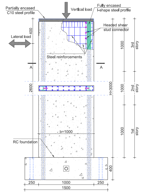
Figure 1: Dimensions of the single story test specimens
2.2 Material Properties
The steel used in the specimens had a yield stress of 325 MPa. This material property was selected so that the frame members would provide sufficient strength while the shear panel would yield first under cyclic loading.
The material behavior was treated as elastic-plastic, which is appropriate for capturing the inelastic response of the dampers during seismic-type loading.
2.3 Experiment Loading Systems
The experiments were conducted under quasi-static cyclic loading. In this type of test, lateral displacement is applied gradually and repeatedly to simulate earthquake-induced deformation.
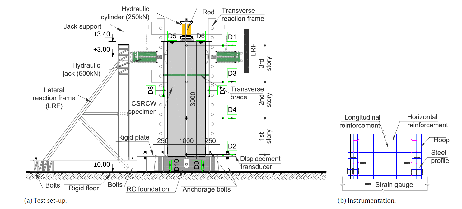
Figure 2: Experiment Loading Systems
2.4 Result of Experiment Test
Concrete Shear Wall in ANSYS APDL
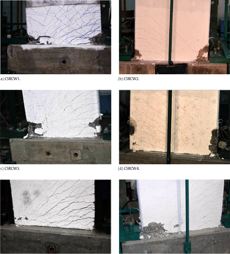
The key performance characteristic of a Concrete Shear Wall, as demonstrated by the test control procedures, is the relationship between the story shear and story drift Or Capacity Curve Of Frame.
3. Finite Element Modeling (ANSYS APDL)
3.1 Overview of ANSYS APDL
ANSYS Parametric Design Language (APDL) is a powerful scripting language used to automate the finite element analysis process. Unlike the standard GUI, APDL allows for high-precision parametric modeling, which is essential for structural validation. It offers advanced capabilities for defining complex geometries, material behaviors, and loading conditions, ensuring that the numerical model accurately represents the experimental setup.
Advantages of using APDL Scripting:
• Automation: Enables seamless iteration of geometry, mesh density, and boundary conditions, supporting complex parametric studies and optimization through scripting.
• Flexibility: Offers precise control over material nonlinearities, advanced contact elements, and custom loading protocols.
Repeatability: Ensures that modeling steps are documented and•
reproducible, reducing human error and crucial for validation studies.
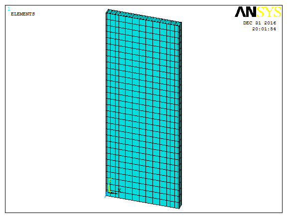
Figure 2: Modeling Experimental Specimen in ANSYS
- Modeling (Step-by-Step)
Step by Step modeling Concrete Shear Wall in ANSYS
Use 2 Real Constant for Supply Thickness of Element
| Topic | No. Real Constant | Value(m) | |
| Beam | Thickness of Web | 1 | 0.0085 |
| Thickness of Flange | 2 | 0.014 |
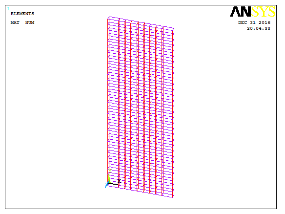
Figure 2: Guide for draw Area by Dimension Method
| Step | Description’s | |
| 1: Element For Beam 2: Element For Column 3: Element For Rebar | 1:SHEEL43[1] 2:Concrete65 3:Link8 | |
| 1: Material For Beam 2: Material For Column 3: Material For Rebar | Material 1 Steel Multilinear Define Material[2] Material 2 Concrete and material 3 is rebar | |
| 3:Modeling | Solid, Area and line Method | |
| 4:Meshing | Quad Mapped | |
| 5:Load, Constraint and Analysis Type | Nonlinear static Analysis by Displacement Control | |
| 6:Result | Plot and Capacity Curve |
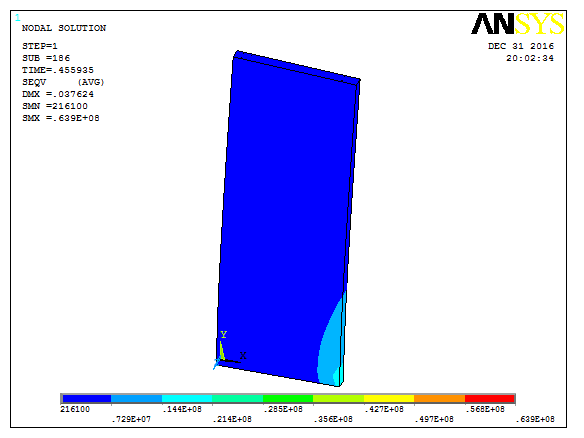
Figure 2: Plot Result after Analysis
Figure 2: Capacity Curve of Finite Element Model Result
4. Results Comparison
4.1 Quantitative Data
Figure 3: Load-Displacement Curve Comparison Graph
The comparison between the experimental and numerical results indicates that the FE model captures the overall structural response with satisfactory accuracy.
| Comparison Parameter | Experimental | FEA Result | Error[3] |
| Result | (ANSYS) | (%) | |
| Peak Load (KN) | 285 | 267.3 | 6.2 |
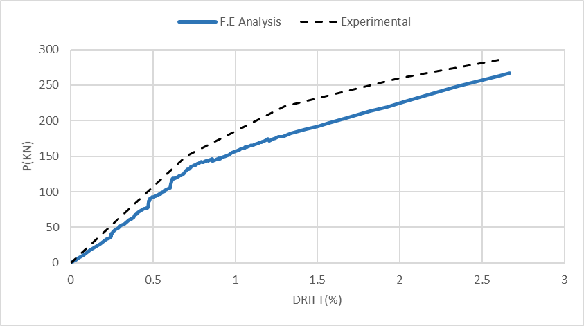
Figure 2: Comparison Between FEM and TEST
The load-displacement trend, peak resistance, and deformation characteristics should be evaluated together to determine the validity of the model.
The most critical validation criterion is whether the FE model can capturein Fig 2 and the ductile cyclic response observed experimentally.
5. Conclusion
The numerical results obtained from the ANSYS APDL model show good agreement with the experimental data. The minor discrepancy in the results validates the reliability of the modeling methodology, confirming that the FE model can be effectively used for further parametric studies.
The paper by Park et al. clearly demonstrates that shear panel dampers are an effective seismic energy-dissipation system for steel frames.
The main conclusions are:
- Steel frames with shear panel dampers show much better cyclic behavior than ordinary frames without dampers.
- The shear panel serves as a sacrificial yielding element and protects the main structural members.
- Stiffeners significantly improve the stability of the damper by preventing premature buckling.
- The finite element results are in good agreement with the experimental observations.
- Among the tested specimens, the stiffened shear panel damper specimen (SF-01) had the best overall seismic performance.
In summary, shear panel dampers can be considered a practical and efficient method for improving the seismic resistance of steel structures, especially when stiffeners are used to enhance stability and ductility.
[1] For More Information See “Define ELEMENT in ANSYS” Tutorial Video
[2] For More Information See “Define MATERIAL in ANSYS” Tutorial Video
| Error (%) = | ∣Experimental Result −FEA Result∣ | × | 100 |
| Experimental Result |
Dan, D., Fabian, A., & Stoian, V. (2011). Nonlinear behavior of composite shear walls with vertical steel encased profiles. Engineering Structures, 33(10), 2850-2861. https://doi.org/10.1016/j.engstruct.2011.04.016
FAQ Section
- What is a Concrete Shear Wall in ANSYS APDL?
- Why is Concrete Shear Wall in ANSYS APDL
- Validation important?
- Which ANSYS elements are used?
- Is the APDL source code included?
- Is the experimental paper included?
Related Validation Projects
Concrete Shear Wall in ANSYS APDL
Lead Rubber Bearing Validation in ANSYS APDL – Download Complete FEM Project