

📑 Table of Contents
📋 Product Overview
📖 Introduction
📊 Validation Results
. Introduction
The seismic performance of structural systems depends strongly on their ability to provide both lateral stiffness and energy dissipation capacity. Conventional moment-resisting frames offer good ductility but may not provide sufficient initial stiffness, while concentrically braced frames can be stiff but often suffer from limited energy dissipation and undesirable brace buckling under strong earthquake loading. For this reason, alternative lateral-force-resisting systems have been developed to combine the advantages of both systems.
The main objective of the referenced research was to evaluate the cyclic and pseudo dynamic behavior of ductile knee braced frames and to demonstrate that shear-yielding knees can provide an efficient seismic-resistant mechanism. The experimental results confirmed that the proposed system had high stiffness in the elastic range and stable hysteretic behavior in the inelastic range.
One such system is the knee braced frame (KBF), which introduces a short linking member, called the knee, between the beam and the brace. This knee element is intentionally designed to yield before the main structural members, thereby acting as a controllable sacrificial fuse. In the study by Balendra et al. (1994), a special form of KBF was investigated in which the knee was designed to undergo shear yielding, rather than flexural yielding, so that stable inelastic deformation could occur without premature brace buckling. This configuration enhances seismic energy dissipation while preserving the integrity of the beam, column, and brace members.
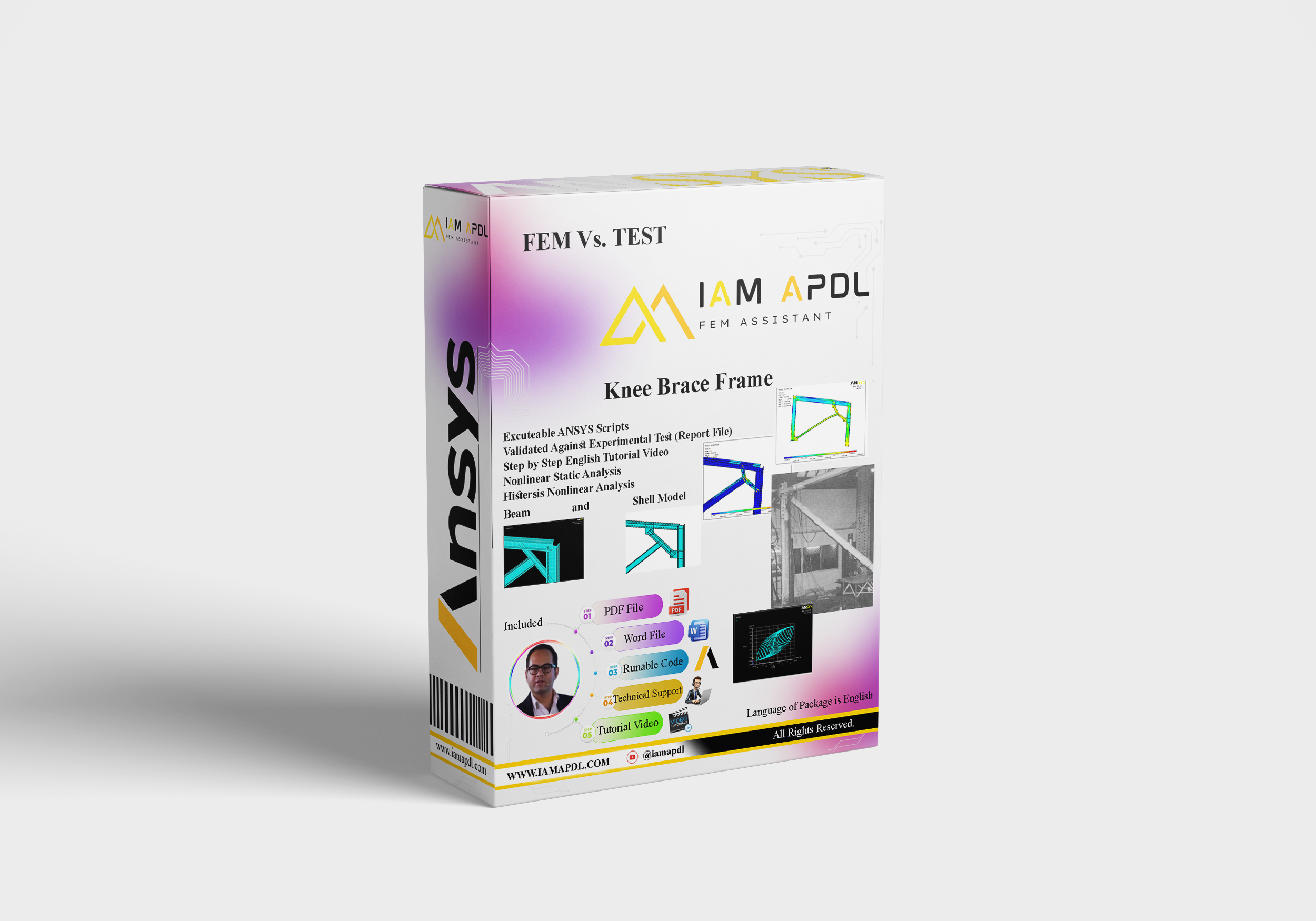
Knee Brace Frame (KBF) Validation in Ansys
Knee braced frames are an efficient structural system for resisting lateral loads, especially in seismic regions. The presence of the knee element allows the brace force to be transferred to the beam through a short deformable segment. Under earthquake loading, the knee acts as the primary energy-dissipating component. If properly detailed, this component can yield in a ductile manner while the rest of the frame remains essentially elastic.
Compared with conventional braced frames, KBFs offer several advantages:
- improved ductility,
- better energy dissipation,
- reduced brace buckling risk,
- easier post-earthquake repair by replacing the damaged knee element.
In the studied system, the knee was intentionally designed to fail in shear. This choice is important because shear yielding can provide a more stable and predictable nonlinear response than flexural yielding. The experimental findings showed that the developed system can be a practical and economical solution for seismic-resistant design.
2. Experimental Specimen Specifications
Knee Brace Frame (KBF) Validation in Ansys
The experimental program included two knee braced frame specimens tested under dynamic loading conditions. The main frame members were selected so that they remained elastic during the tests, while the knee element was designed as the yielding fuse.
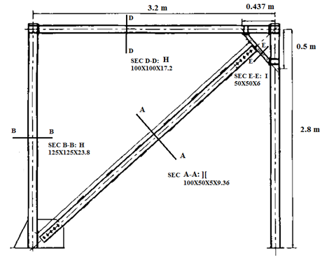
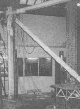
2.1 Geometric Properties
The beam and column members were made of WF sections:
- Beam: 100 × 100 × 17.2 mm
- Column: 125 × 125 × 23.8 mm
The brace member was composed of:
- In Diagonal member: two channel sections 100 × 50 × 5 × 9.36 mm
- arranged back-to-back with a 16 mm gap
- connected using batten plates at 500 mm intervals
The knee member was fabricated as an I-section of 50 × 50 mm and was designed to yield in shear. The distance from the knee-brace connection to the knee-column connection was 180 mm, and the distance from the knee-brace connection to the knee-beam connection was 130 mm.
Two knee configurations were investigated:
- Experimental Specimen: with two web stiffeners
This geometric arrangement ensured that the knee was the weakest and most ductile part of the system.
Figure 1: Dimensions of the single story test specimens
2.2 Material Properties
The material properties used in the experimental specimens were reported separately for the two tests.
Yield stress: 337 N/mm²
Young’s modulus: 200 kN/mm²
These properties indicate that the steel members had sufficient strength and stiffness for the frame to remain elastic, while allowing the knee section to undergo controlled inelastic deformation. The similar hardening ratios in both tests imply a comparable post-yield response.
2.3 Experiment Loading Systems
The specimens were tested using a pseudo dynamic loading system. The setup included:
- a central microcomputer control unit,
- hydraulic jack,
- load cell,
- displacement transducers,
- and strain gauges including linear gauges and rectangular rosettes.
The displacement transducers were used to monitor:
- the vertical displacement at the beam-knee connection,
- and the out-of-plane movement at the brace-knee connection.
Before the dynamic tests, static tests were carried out to determine the elastic stiffness of the system. Free-vibration tests were also performed to estimate internal damping. After that, forced dynamic tests were conducted in the elastic range, followed by inelastic excitation to push the structure beyond yield.
The base excitation was sinusoidal with:
- frequency: 20 rad/s
- initial acceleration amplitude: 0.75 m/s²
- increment: 0.225 m/s² every three cycles
A viscous damping ratio of 2% of critical damping was assumed in the analysis.
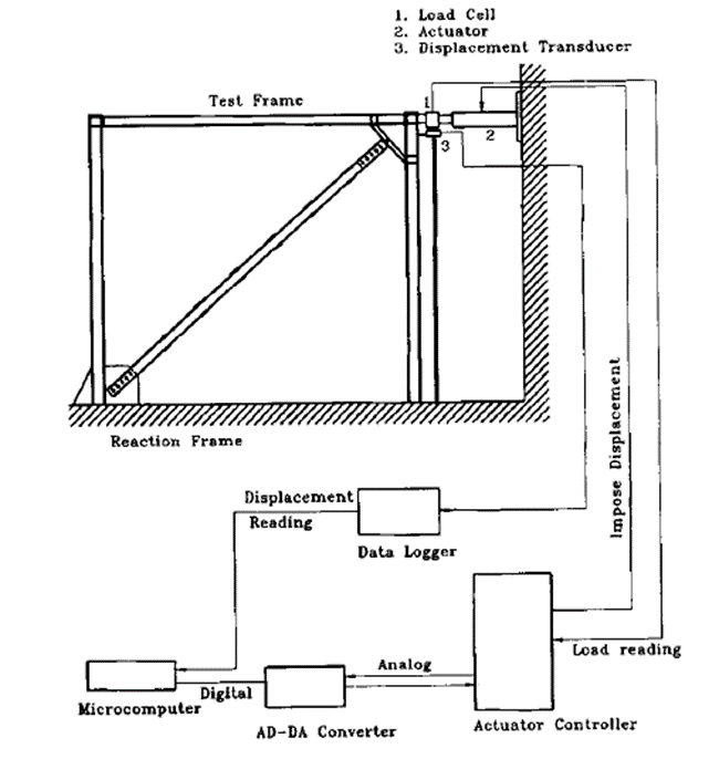
Figure 2: Experiment Loading Systems
2.4 Result of Experiment Test
Knee Brace Frame (KBF) Validation in Ansys
The key performance characteristic of a Knee Brace Frame (KBF), as demonstrated by the test control procedures, is the relationship between the story shear and story drift Or Capacity Curve Of Frame.
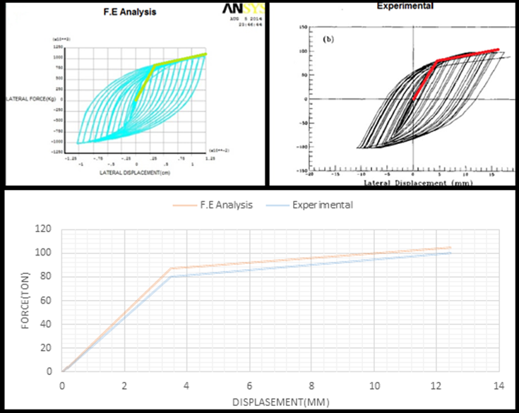
Figure 2: Capacity Curve of Experimental Test Result
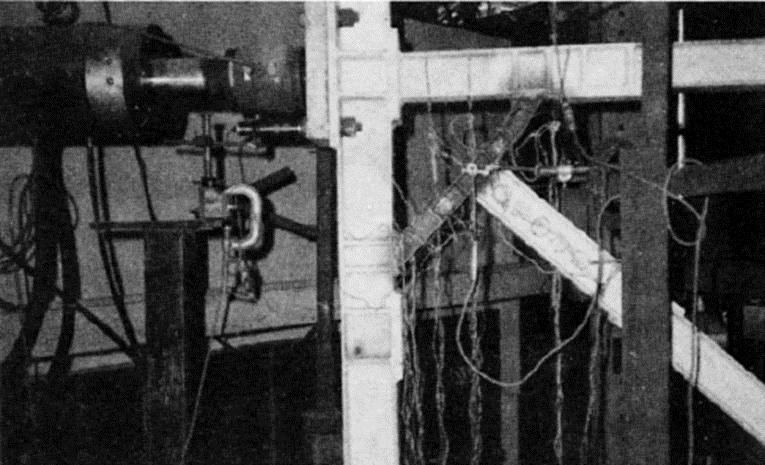
Figure 2: Experiment Loading Systems
3. Finite Element Modeling (ANSYS APDL)
3.1 Overview of ANSYS APDL
Knee Brace Frame (KBF) Validation in Ansys
ANSYS Parametric Design Language (APDL) is a powerful scripting language used to automate the finite element analysis process. Unlike the standard GUI, APDL allows for high-precision parametric modeling, which is essential for structural validation. It offers advanced capabilities for defining complex geometries, material behaviors, and loading conditions, ensuring that the numerical model accurately represents the experimental setup.
Advantages of using APDL Scripting:
• Automation: Enables seamless iteration of geometry, mesh density, and boundary conditions, supporting complex parametric studies and optimization through scripting.
• Flexibility: Offers precise control over material nonlinearities, advanced contact elements, and custom loading protocols.
Repeatability: Ensures that modeling steps are documented and•
reproducible, reducing human error and crucial for validation studies.
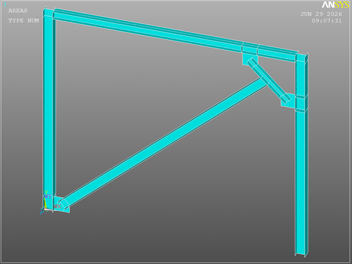
Figure 2: Modeling Experimental Specimen in ANSYS
- Modeling (Step-by-Step)
Step by Step modeling Knee Brace Frame (KBF) Validation in Ansys
Use 6 Real Constant for Supply Thickness of Element
| Topic | No. Real Constant | Value(m) | |
| Column | Thickness of Web | 1 | 0.0238 |
| Thickness of Flange | 2 | 0.0238 | |
| Beam | Thickness of Web | 3 | 0.0172 |
| Thickness of Flange | 4 | 0.0172 | |
| Diagonal Brace | Thickness of Web | 5 | 0.008 |
| Thickness of Flange | 6 | 0.01 | |
| Knee Member | Thickness of Web | 7 | 0.008 |
| Thickness of Flange | 8 | 0.008 |
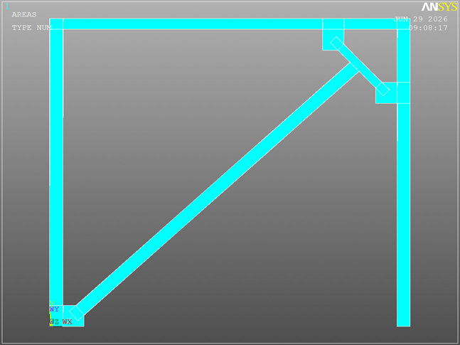
Figure 2: Guide for draw Area by Dimension Method
| Step | Description’s | |
| 1: Element For Column, Beam, Diagonal and Knee Member | SHEEL43[1] | |
| 2:Material For Column, Beam, Diagonal and Knee Member | Material 1 Define Multilinear Material[2] | |
| 3:Modeling | Area Method | |
| 4:Meshing | Quad Mapped | |
| 5:Load, Constraint and Analysis Type | Nonlinear static Analysis by Displacement Control | |
| 6:Result | Plot and Capacity Curve |
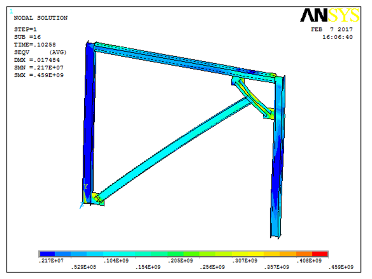
Figure 2: Plot Result after Analysis
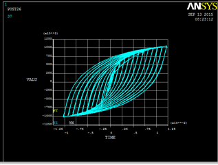
Figure 2: Capacity Curve of Finite Element Model Result
4. Results Comparison
4.1 Quantitative Data
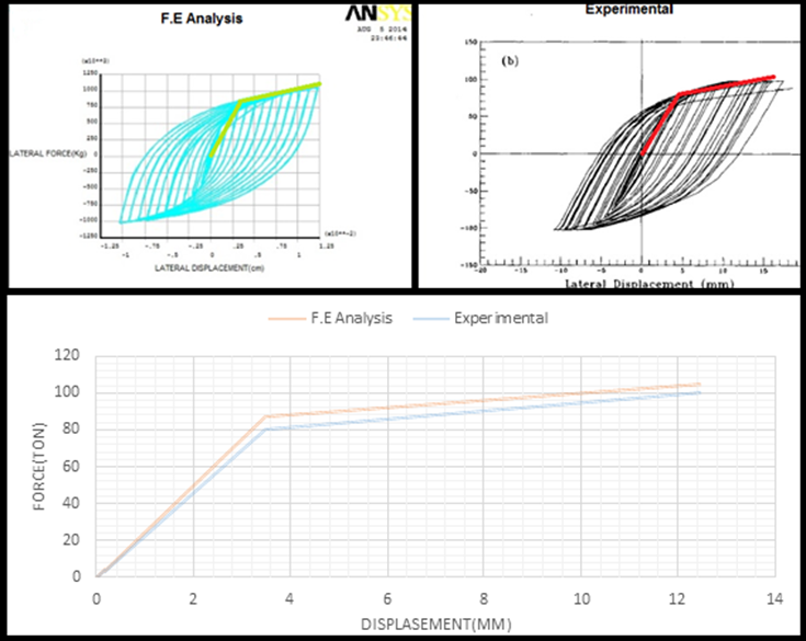
Figure 3: Load-Displacement Curve Comparison Graph
The comparison between the experimental and numerical results indicates that the FE model captures the overall structural response with satisfactory accuracy.
| Comparison Parameter | Experimental | FEA Result | Error[3] |
| Result | (ANSYS) | (%) | |
| Peak Load (Ton) | 101 | 104.4 | 3.4 |
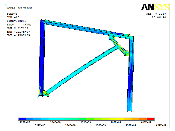
Figure 2: Comparison Between FEM and TEST
The load-displacement trend, peak resistance, and deformation characteristics should be evaluated together to determine the validity of the model.
If required, the percentage error may be computed using:
A low error percentage suggests that the selected element formulation, material models, and boundary conditions are appropriate for representing the tested specimen. The hysteretic loops obtained from the tests were stable and well-defined, indicating good energy dissipation capacity. The absence of severe pinching suggests that the load transfer mechanism through the knee was effective. The cyclic response demonstrated that the structure could sustain repeated loading without sudden loss of strength.
For a numerical model, the following behaviors should be reproduced:
- initial stiffness,
- yield point,
- post-yield softening or hardening,
- loop shape,
- residual deformation,
- and ultimate failure mode.
The most critical validation criterion is whether the FE model can capture the knee web tearing and the ductile cyclic response observed experimentally.
5. Conclusion
The numerical results obtained from the ANSYS APDL model show good agreement with the experimental data. The minor discrepancy in the results validates the reliability of the modeling methodology, confirming that the FE model can be effectively used for further parametric studies.
[1] For More Information See “Define ELEMENT in ANSYS” Tutorial Video
[2] For More Information See “Define MATERIAL in ANSYS” Tutorial Video
| Error (%) = | ∣Experimental Result −FEA Result∣ | × | 100 |
| Experimental Result |
Balendra, T., Lim, E. L., & Lee, S. L. (1994). Ductile knee braced frames with shear yielding knee for seismic resistant structures. Engineering Structures, 16(4), 263-270. DOI: 10.1016/0141-0296(94)90013-2
FAQ Section
- What is Knee Brace Frame (KBF) Validation in Ansys
- Which ANSYS elements are used?
- Is the APDL source code included?
- Is the experimental paper included?